Output control method of pulse arc welding
A technology of output control and pulsed arc, which is applied in the direction of arc welding equipment, welding equipment, manufacturing tools, etc., can solve the problems of arc length control system stability and poor transition response, and achieve good transition response and droplet transition Good condition, good stability effect
- Summary
- Abstract
- Description
- Claims
- Application Information
AI Technical Summary
Problems solved by technology
Method used
Image

Examples
Embodiment approach 1
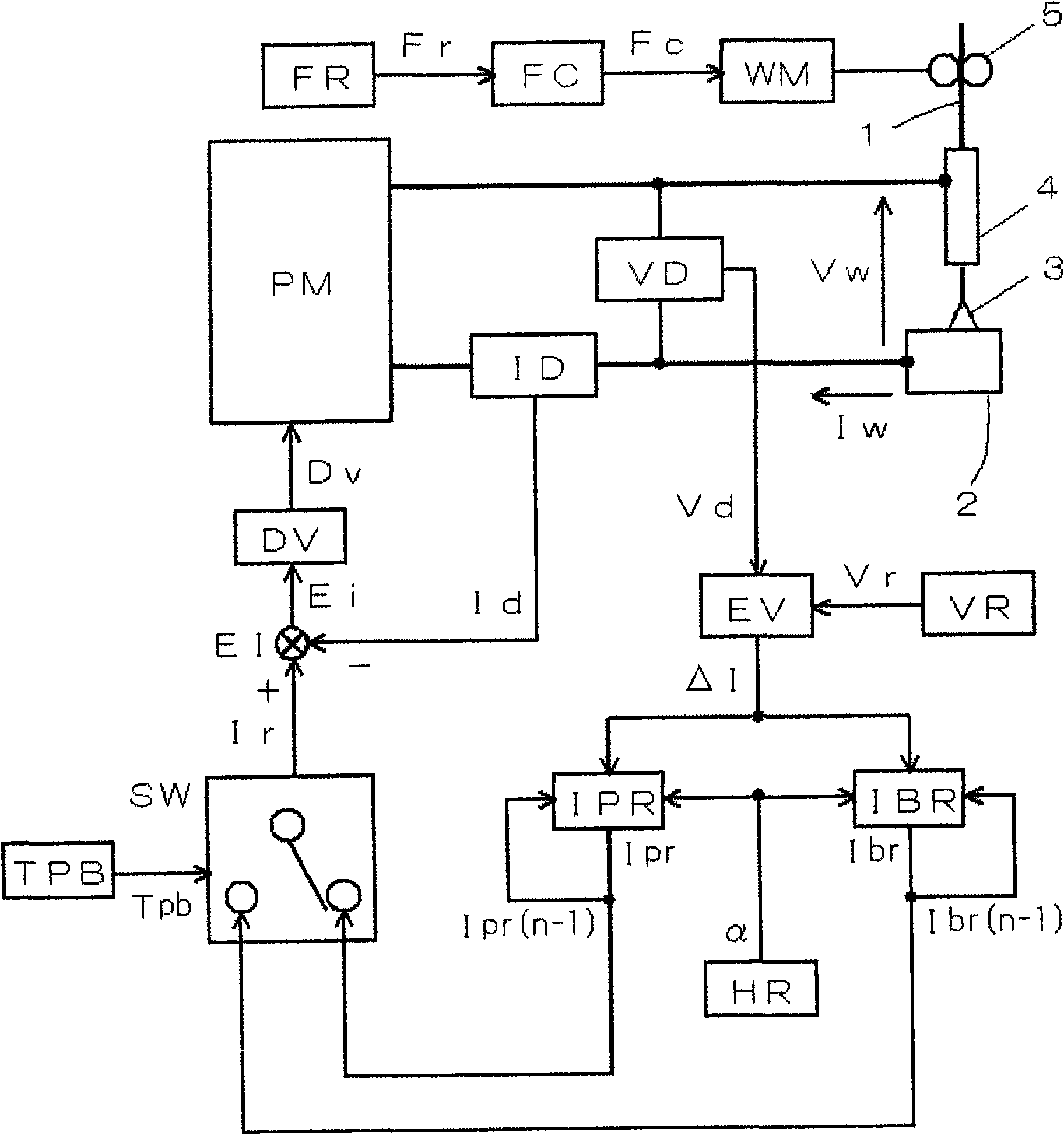
[0109] figure 1 It is a block diagram of the welding power source for implementing the output control method of the pulse arc welding concerning Embodiment 1 of this invention. Hereinafter, each block diagram will be described with reference to this figure.
[0110] The power supply main circuit PM receives a commercial power supply (not shown) such as 3-phase 200V, performs output control by inverter control according to a drive signal Dv described later, and outputs welding current Iw and welding voltage Vw. This power supply main circuit PM is not shown, but includes a primary rectifier that rectifies commercial power, a capacitor that smoothes the rectified DC, and an inverter that converts the smoothed DC into high-frequency AC according to the above-mentioned drive signal Dv. It consists of a transformer circuit, a high-frequency transformer that steps down high-frequency AC to a voltage suitable for arc welding, a secondary rectifier that rectifies the stepped-down hi...
Embodiment approach 2
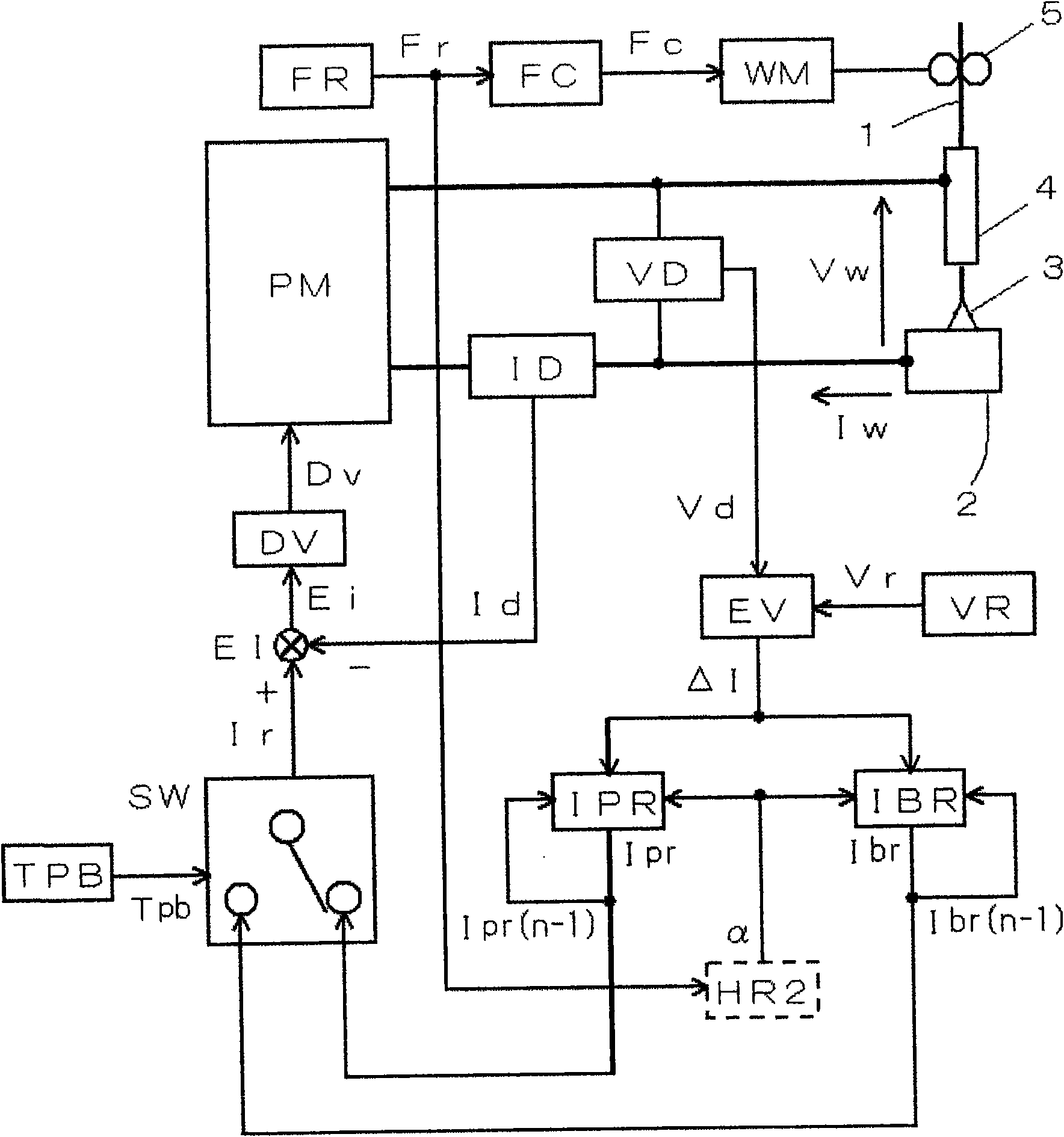
[0126] figure 2 It is a block diagram of the welding power source for implementing the output control method of the pulse arc welding concerning Embodiment 2 of this invention. In this figure, for the above figure 1 The same modules are assigned the same symbols, and their descriptions are omitted. Hereinafter, referring to the figure, for the figure 1 The second distribution ratio setting circuit HR2 shown by a different dotted line will be described.
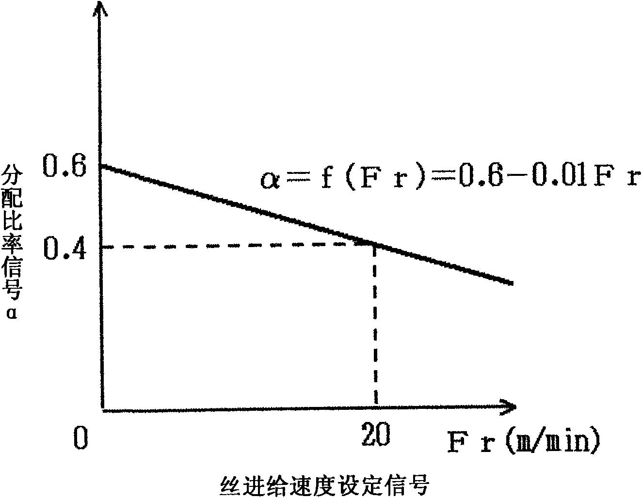
[0127] The second distribution ratio setting circuit HR2 receives the wire feed speed setting signal Fr as an input, and outputs a distribution ratio signal α according to a predetermined function α=f(Fr). image 3 An example of this function is shown in . In this figure, the horizontal axis represents the wire feed speed setting signal Fr (m / min), and the vertical axis represents the distribution ratio signal α. As shown in the figure, the function f(Fr) becomes a straight line descending to the right with α=0.6 when ...
Embodiment approach 3
[0131] Figure 4 It is a current-voltage waveform diagram showing the output control method of the pulse arc welding according to Embodiment 3 of the present invention. This figure (A) shows the welding current Iw which energizes an arc, and this figure (B) shows the welding voltage Vw between a welding wire and a base metal. This figure shows the case of AC pulse arc welding in which part of the reference period is in the electrode negative polarity period. In this figure, the upper side of 0A and 0V is the electrode positive polarity EP, and the lower side is the electrode negative polarity EN. Hereinafter, description will be made with reference to this figure.
[0132] During the predetermined electrode negative polarity reference period Tn from time t1 to t2, as shown in (A) of the figure, an electrode negative polarity reference current In of a constant current value is energized in order not to form a droplet, as shown in (B) of the figure , apply the electrode negat...
PUM
 Abstract
Description
Claims
Application Information
 - R&D Engineer
- R&D Manager
- IP Professional
- Industry Leading Data Capabilities
- Powerful AI technology
- Patent DNA Extraction
Browse by: Latest US Patents, China's latest patents, Technical Efficacy Thesaurus, Application Domain, Technology Topic.
© 2024 PatSnap. All rights reserved.Legal|Privacy policy|Modern Slavery Act Transparency Statement|Sitemap