Reinforcing bar binder

A technology of strapping machine and steel bar, applied in construction, building structure, construction material processing and other directions, can solve problems such as poor torsion, increased friction, reduced lubrication function, etc. The effect of the number of parts

Active Publication Date: 2009-11-25
MAX CO LTD
View PDF0 Cites 29 Cited by
  • Summary
  • Abstract
  • Description
  • Claims
  • Application Information

AI Technical Summary

Problems solved by technology

In such a case, the lubricating function is reduced, and the friction force between the sleeve and the above-mentioned parts increases, so that the sleeve cannot rotate with the front shaft, and the phenomenon that the hook cannot return to the standby position is likely to occur.
Since the hook is not oriented correctly when the hook cannot return to the standby position, the wire cannot be held during the twisting action, and twisting failure may occur
In order to prevent such a phenomenon, it is necessary to use a thick compression spring with a large spring load, or to increase the frictional force between the sleeve and the front shaft by adding an additional part, and there is a problem that the device becomes large and complicated, resulting in an increase in cost.

Method used


Image

  • Reinforcing bar binder
  • Reinforcing bar binder
  • Reinforcing bar binder

Examples


Embodiment Construction

[0061] Typical embodiments of the present invention will be described with reference to the drawings.

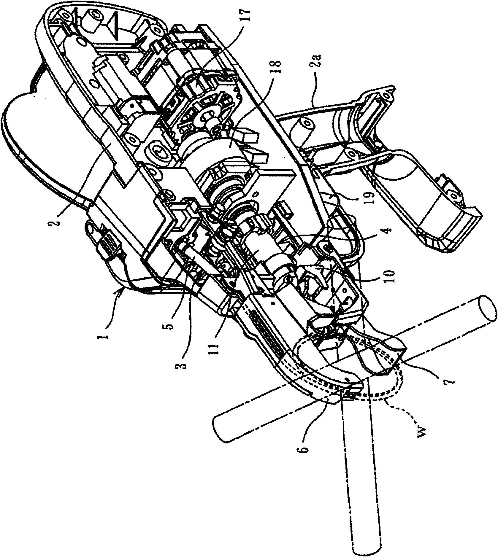
[0062] figure 1 It is a perspective view showing the internal state of the steel bar binding machine. The steel bar binding machine 1 is equipped with a steel wire feeding device 3 and a steel wire binding device 4 in a casing 2, and a steel wire is rotatably pivotally mounted on the rear side of the casing 2. reel (not shown).

[0063] On the steel wire feeding device 3, the steel wire w wound on the steel wire reel is sent from the guide pipe 5 to the steel wire guide 6 through a feed roller not shown in the figure, where it is coiled, and between the lower guide 7 A device that is wound around a steel bar (not shown) in an annular shape. The steel wire binding device 5 is a device that grasps a part of the annular steel wire w and twists and binds it. cut off.

[0064] The steel wire feeding device 3 and the steel wire binding device 4 are sequentially controlled by a...


PUM


Abstract

A reinforcing bar binding machine is provided with: a main sleeve (11) having a tip end on which a hook (10) is pivotally mounted; a tip end shaft (12) fitted in an inside of the main sleeve (11); a spiral screw groove (14) formed on the tip end shaft (12); a fitting opening (13) that penetrates from an outside to the inside of the main sleeve (11); a key (15) fitted in the fitting opening (13) and brought in mash engagement with the screw groove (14); a short sleeve (16) provided on an outer periphery of the main sleeve (11) and covering the key (15); and an engaging means (33,34) formed on the short sleeve (16) and controlling a rotation of the main sleeve (11).

Description

technical field [0001] The present invention relates to a steel bar binding machine provided with a binding device that twists and binds a steel wire wound around a steel bar arranged in a ring shape. Background technique [0002] A reinforcing bar binding machine is known as a tool for binding reinforcing bars at crossings of reinforcing bars and the like in a reinforcing bar arrangement process of reinforced concrete construction. The steel bar binding machine is provided with a binding device for binding steel bars. As shown in Japanese Patent No. 3496463, there is provided a steel bar binding machine, which has: a sleeve provided inside the main body of the binding machine and pivotally mounted with a hook for binding steel bar at the front end freely rotatable, fitted inside the sleeve And the front-end shaft that generates the load of the front-back movement and rotation of the sleeve, and the engagement unit (fin) that controls the rotation of the sleeve in cooperati...

Claims


Application Information

Patent Timeline
Patent Type & Authority Applications(China)
IPC IPC(8): E04G21/12
CPCE04G21/123
Inventor 长冈孝博小林刚
Owner MAX CO LTD
Why Eureka
Try Eureka