Lamp for vehicle

A technology for vehicles and lamps, used in lighting and heating equipment, point light sources, lighting devices, etc.

Inactive Publication Date: 2009-11-25
ICHIKOH IND LTD
View PDF3 Cites 1 Cited by
  • Summary
  • Abstract
  • Description
  • Claims
  • Application Information

AI Technical Summary

Problems solved by technology

Moreover, in terms of vehicle design, if components such as reflectors and inner panels in the lamp chamber protrude to the side of the lamp lens, the light from the light source toward the side of the vehicle will be protruded to the inner panels and other components on the side of the lamp lens. Shading, making it difficult to reliably shine light from a light source to the sides of the vehicle

Method used


Image

  • Lamp for vehicle
  • Lamp for vehicle
  • Lamp for vehicle

Examples


Embodiment Construction

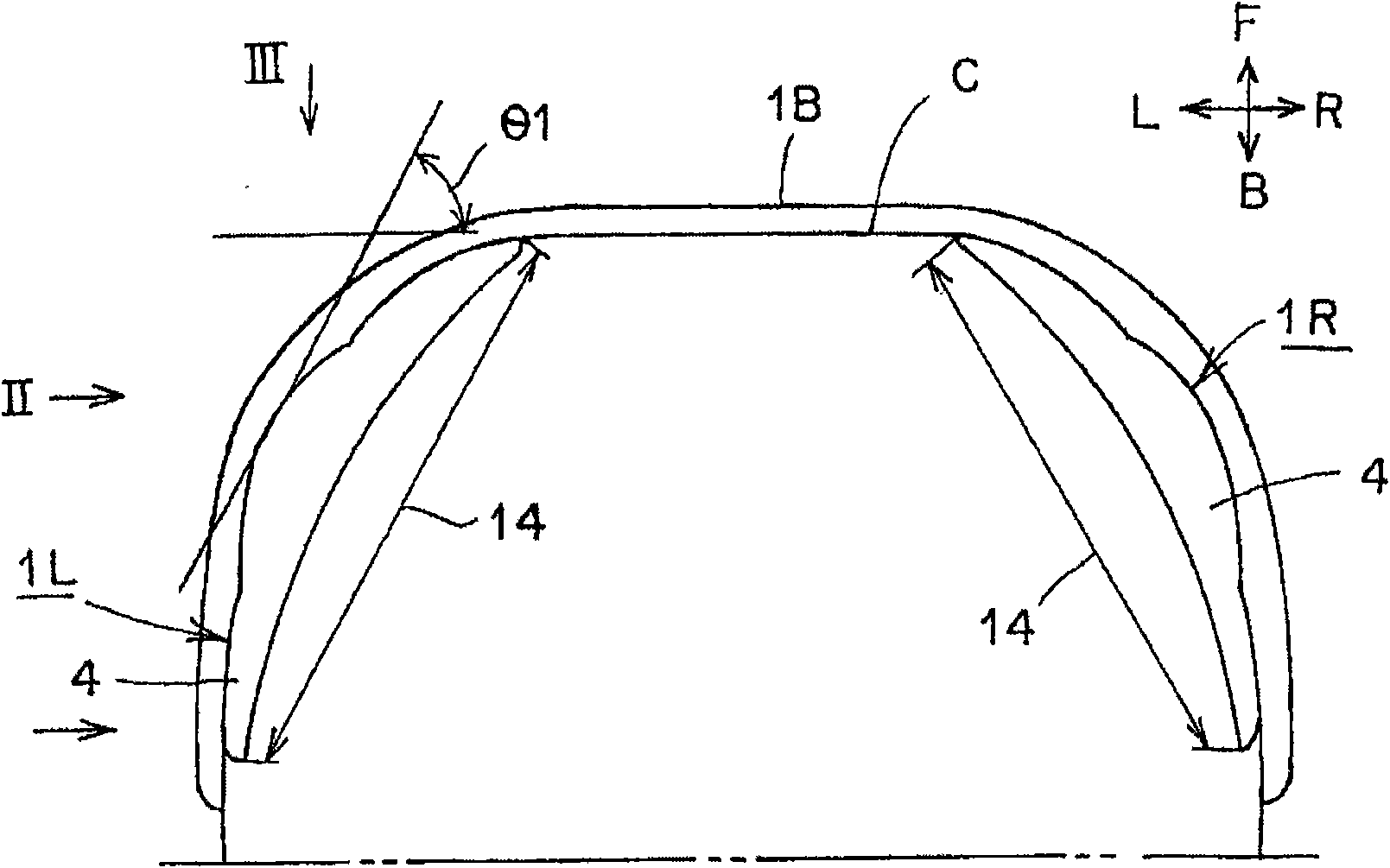
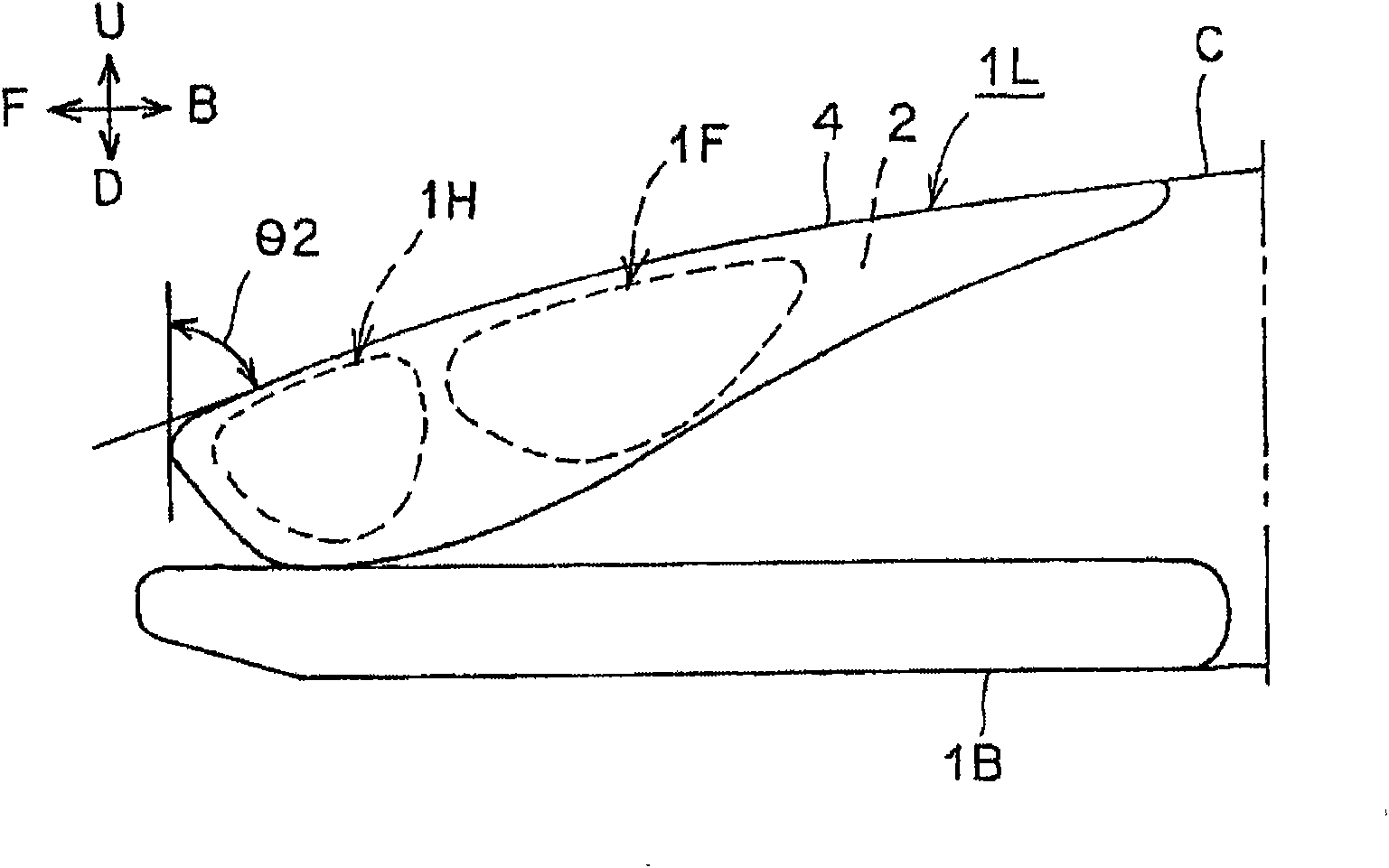
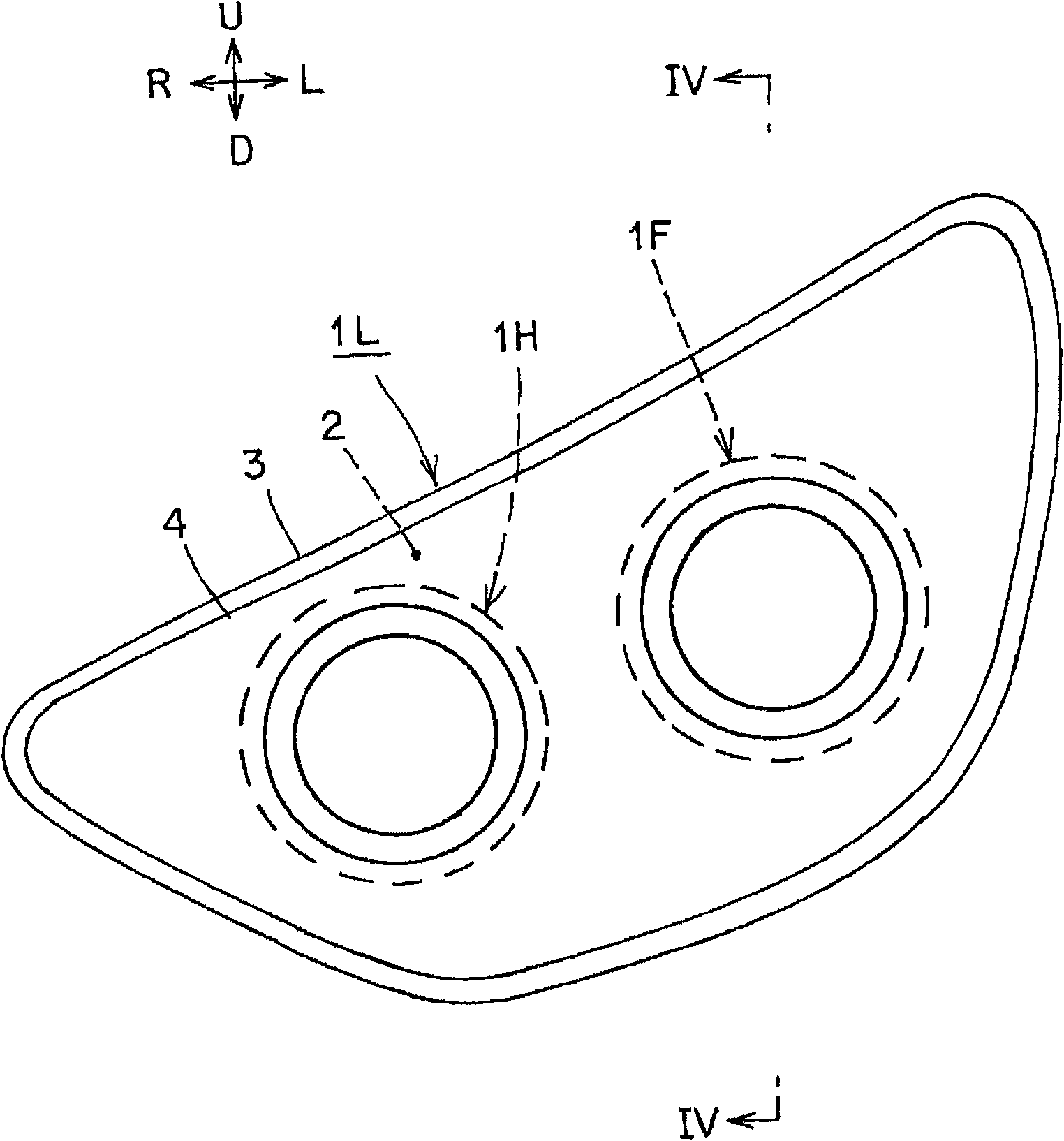
[0034]Hereinafter, embodiments of the vehicle lamp according to the present invention will be described in detail based on the drawings. In addition, this invention is not limited to this Example. In the drawings, symbol "F" denotes the front side of the vehicle (the side in the forward direction of the vehicle). Symbol "B" indicates the rear side of the vehicle. The symbol "U" indicates the upper side of the front side viewed from the driver's side. Symbol "D" indicates the lower side of the front side viewed from the driver's side. The symbol "L" indicates the left side when looking at the front side from the driver's side. The symbol "R" indicates the right side as viewed from the driver's side on the front side. The aforementioned front, rear, upper, lower, left, and right are front, rear, upper, lower, left, and right when the vehicle lamp according to the present invention is mounted on a vehicle. In addition, the symbol "VU-VD" represents the vertical lines above a...


PUM


Abstract

The invention provides a lamp for vehicle, capable of reliably leading the light from the light source to the side of the vehicle. the lamp comprises a first reflector (6) and a second reflector (7). The light from the light source (5) irradiates from the front to the side of the vehicle under the action of the first reflector (6) to form a first light-distributing pattern (P1), a opening ( 16) ia arranged on the first reflector (6). The light from the light source (5) going through the opening (16) of the first reflector is reflected to the side of the vehicle (C) by the second reflector (7) to form a second light-distributing pattern (P2). As the result, the invention can reliably lead the light from light source (5) to the side of the vehicle (C).

Description

technical field [0001] The present invention relates to a vehicle lamp that irradiates light to the front and side of a vehicle, or to the rear and the side. Background technique [0002] Vehicle lamps that emit light to the front and side of the vehicle or to the rear and the side have been known (for example, refer to Patent Document 1, Patent Document 2, and Patent Document 3). Hereinafter, conventional vehicle lamps will be described. A conventional vehicle lamp includes a lamp housing and a lamp lens that define a lamp chamber, and a light source and an auxiliary reflector or a light guide disposed in the lamp chamber. [0003] Hereinafter, the operation of a conventional vehicle lamp will be described. When the light source is turned on, the light from the light source is irradiated from the front to the side of the vehicle or from the rear to the side through the lamp lens. On the other hand, the light from the light source is irradiated to the side of the vehicle ...

Claims


Application Information

Patent Timeline
Patent Type & Authority Applications(China)
IPC IPC(8): F21S8/10F21V5/04F21V7/04F21V7/10F21W101/10F21W101/12F21Y101/00
Inventor 塚田博之
Owner ICHIKOH IND LTD
Why Eureka
Try Eureka