Display unit

A technology for a display device and a display area, which is applied in nonlinear optics, instruments, optics, etc., and can solve the problems of being unable to design with a narrow frame and affecting the display effect of a display device 10, etc.

Active Publication Date: 2011-01-26
AU OPTRONICS CORP
View PDF0 Cites 0 Cited by
  • Summary
  • Abstract
  • Description
  • Claims
  • Application Information

AI Technical Summary

Problems solved by technology

[0004] Depend on figure 1 It can be seen that the gate lines 14 of the conventional display device 10 are electrically connected to the driving chip 20 through the connecting wires 18 arranged in the peripheral area 12P, but because the connecting wires 18 located in the peripheral area 12P are connected to the scanning lines 14 located in the display area 12D Different from the load effect generated by the data line 16, it will affect the display effect of the display device 10
In addition, in order to arrange the connection wires 18, the existing display device 10 must have a relatively large peripheral area 12P, so it cannot have a narrow frame design.

Method used


Image

  • Display unit
  • Display unit
  • Display unit

Examples


Embodiment Construction

[0027] In order to enable those who are familiar with the technical field of the present invention to further understand the present invention, several preferred embodiments of the present invention are listed below, together with the accompanying drawings, to describe in detail the composition of the present invention and the desired effects .

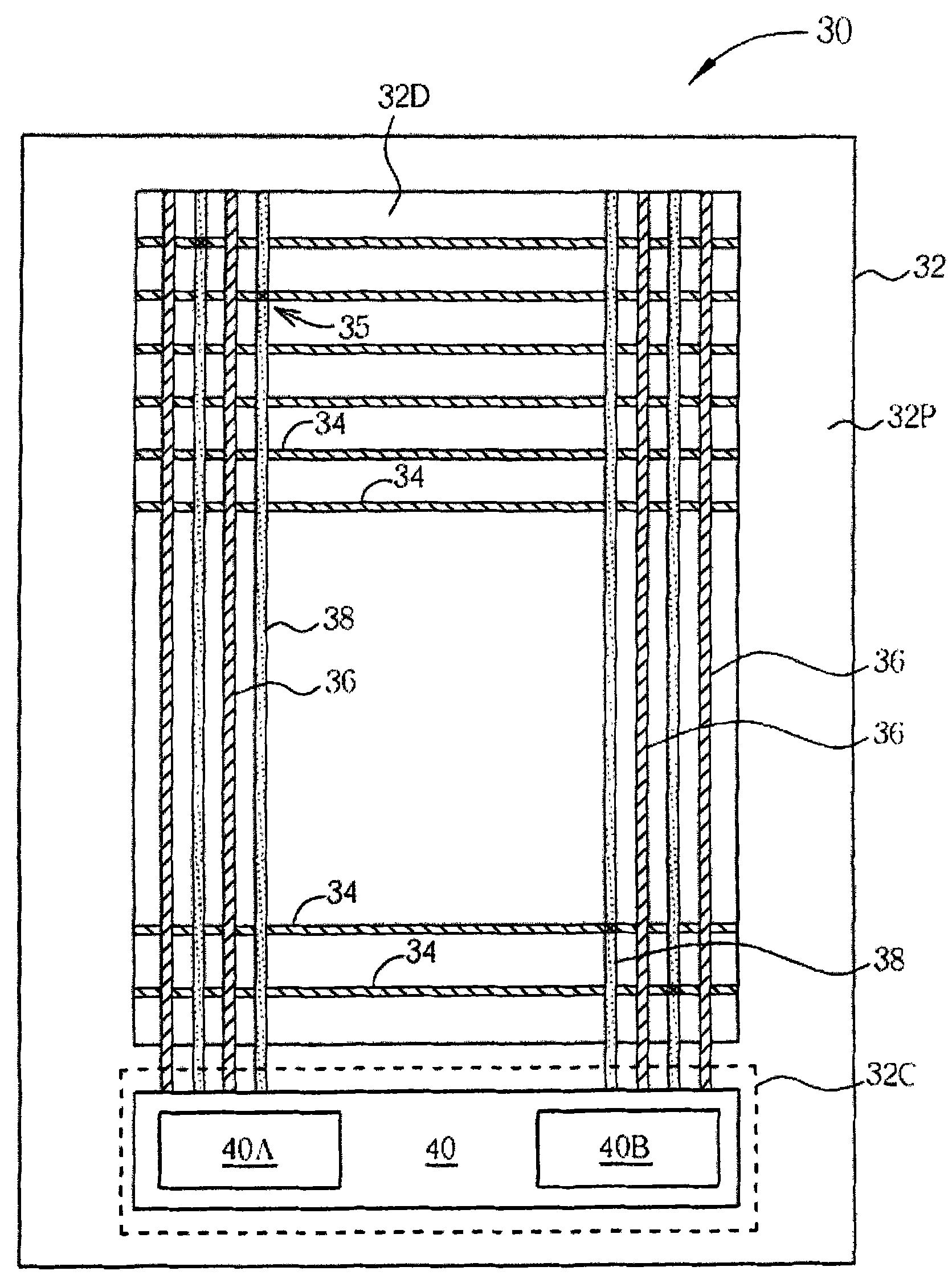
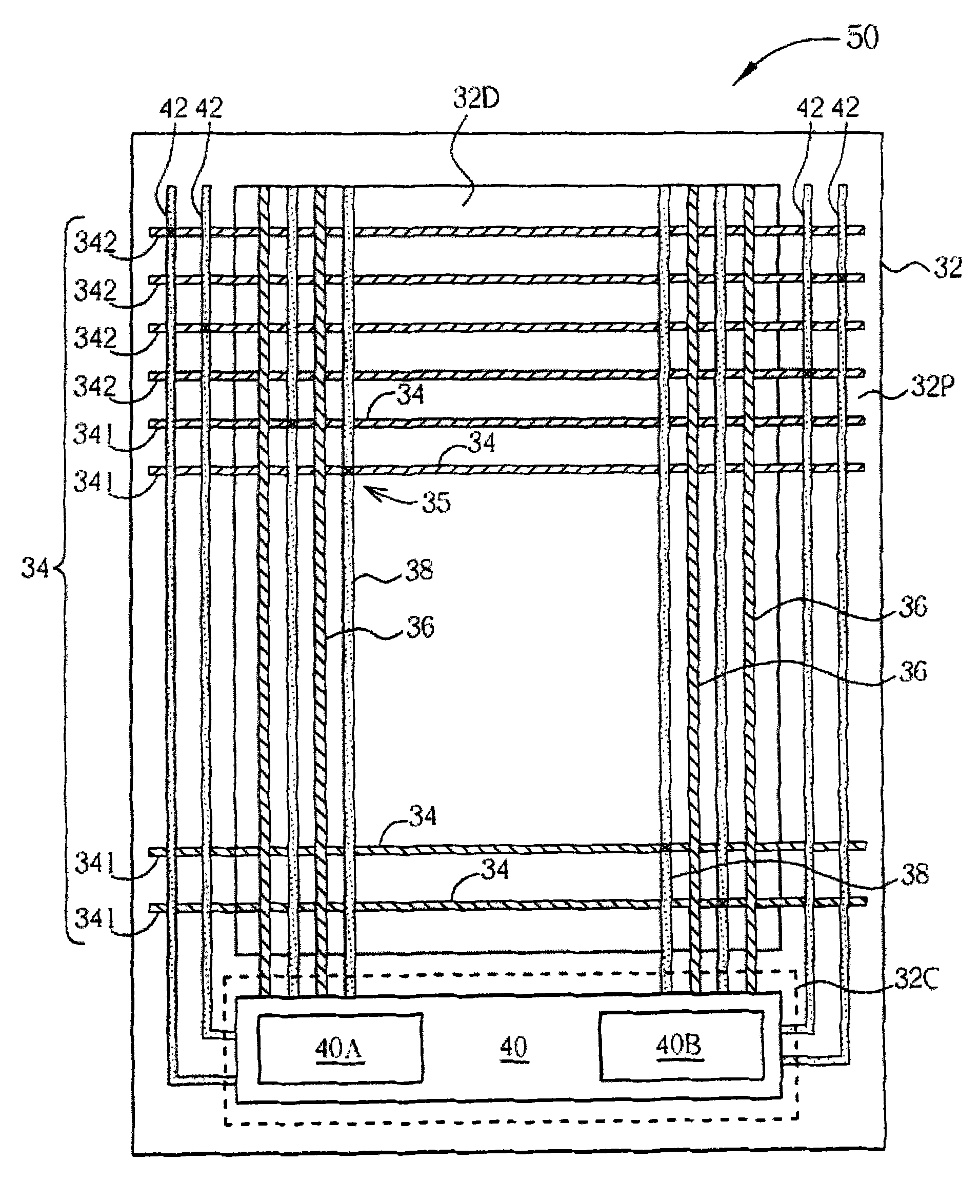
[0028] Please refer to figure 2 . figure 2 A schematic diagram of a display device according to a first preferred embodiment of the present invention is shown. Such as figure 2 As shown, the display device 30 of this embodiment includes a substrate 32 , and the substrate 32 includes a display area 32D, a peripheral area 32P and a chip connection area 32C. In this embodiment, the display device 30 may be a liquid crystal display device, but not limited thereto, and may be other types of display devices. The display device 30 includes a plurality of first signal lines 34, a plurality of second signal lines 36, and a plurality of ...


PUM


Abstract

A display unit comprises a substrate, a plurality of first signal lines, a plurality of second signal lines and a plurality of first signal internal switching lines. The first and second lines are arranged in the display zone of the substrate in the manner of interlacement. The first signal internal switching lines are arranged in the display zone of the substrate, wherein each first signal internal switching line is electrically connected to a corresponding first signal line and arranged between the adjacent second signal lines. Each first signal internal switching line is intersected with afirst signal line and has the same cross point with the first signal line. The invention causes all the signal lines to have the same loading effect by changing the configuration of signal lines or regulating the RC delay of partial signal lines, thus, the display unit will not have the bad effect on the display quality due to the non-uniform loading effect. The narrow-frame display unit can be achieved by setting the internal switching line by the display unit.

Description

technical field [0001] The present invention relates to a display device, especially a display device with a uniform load effect. Background technique [0002] A display device, such as a liquid crystal display device, includes wires or electrode structures such as gate lines, common lines, data lines, and pixel electrodes disposed on a substrate. In the line layout, whether it is due to design or under some unavoidable factors, the horizontal distance between the wires will be too close, so that the signals between each other will affect each other, resulting in a load effect. When the loading effect is not uniformly generated on each pixel, the effect on each pixel will not be consistent, and the uneven loading effect will seriously affect the display quality. Therefore, in the design of the display device, the uneven loading effect should be avoided as much as possible. [0003] Please refer to figure 1 . figure 1 A schematic diagram of a conventional display device i...

Claims


Application Information

Patent Timeline
Patent Type & Authority Patents(China)
IPC IPC(8): G02F1/1345
Inventor 李忠隆王仓鸿刘圣超
Owner AU OPTRONICS CORP
Why Eureka
Try Eureka