Drive circuit of fluorescent display
A technology for driving circuits and displays, applied to static indicators, light sources, instruments, etc., can solve the problem of not generating reactive power
- Summary
- Abstract
- Description
- Claims
- Application Information
AI Technical Summary
Problems solved by technology
Method used
Image

Examples
Embodiment Construction
[0023] By referring to Figure 1 to image 3 Embodiments of the present invention will be explained. Similarly, in Figure 1 to image 3 In , common parts use the same reference numerals.
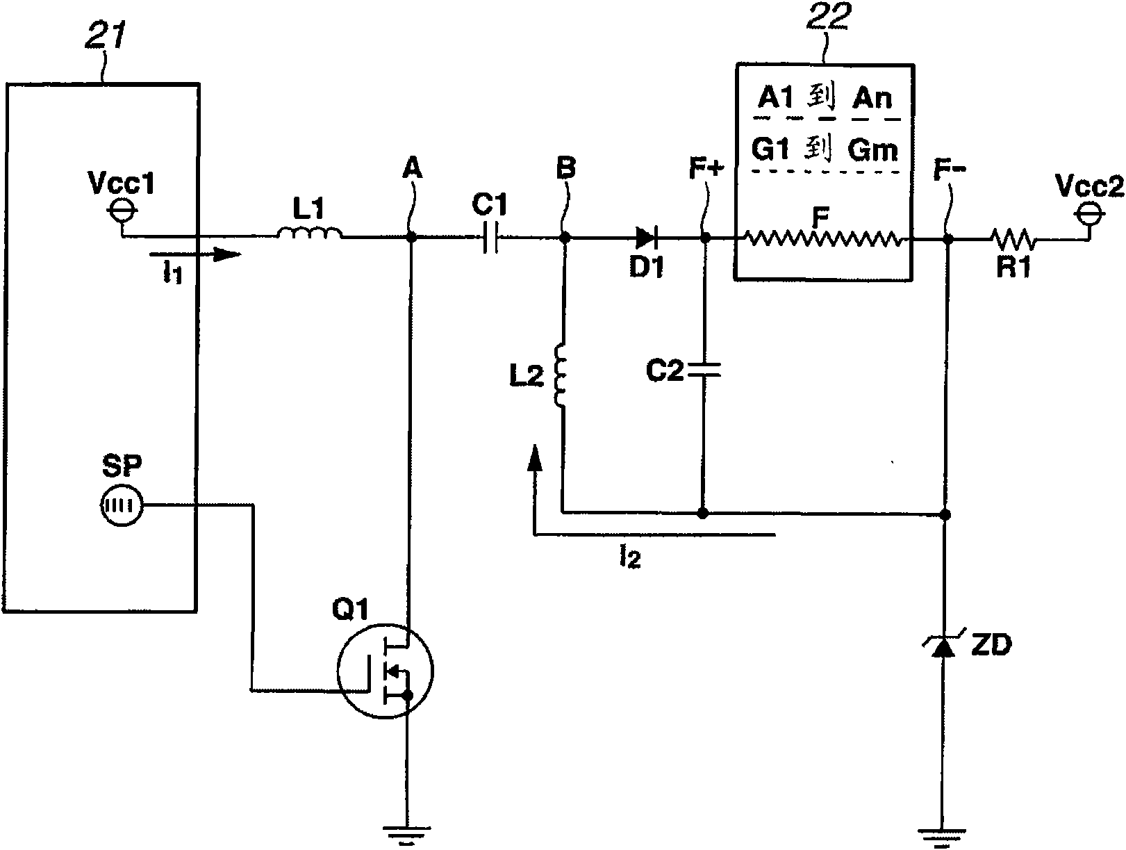
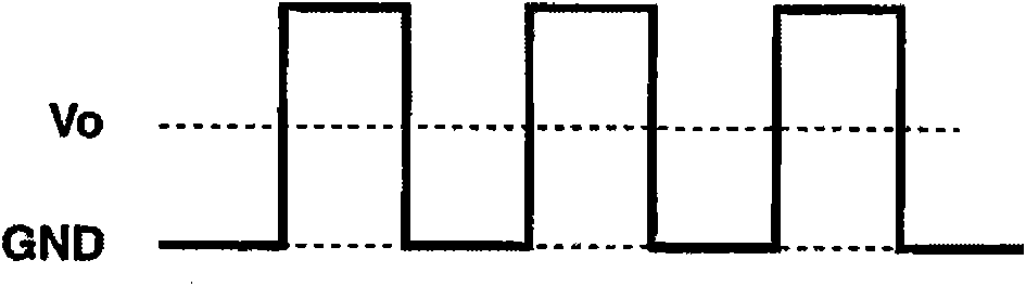
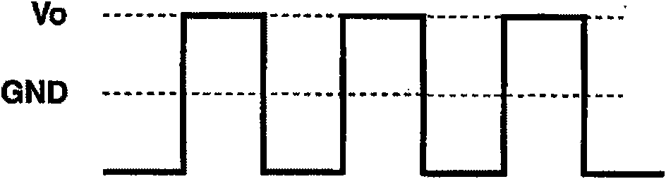
[0024] First, explain Figure 1. Figure 1(a) shows a driving circuit for a fluorescent display. FIG. 1( b1 ) shows the potential at point A in the drive circuit of FIG. 1( a ). Fig. 1(b2) shows the potential at point B in the drive circuit of Fig. 1(a). FIG. 1( b3 ) shows currents of inductors L1 and L2 in the driving circuit of FIG. 1( a ). FIG. 1( b4 ) shows the on-off state of the switching element Q1 in the drive circuit of FIG. 1( a ).
[0025] As shown in FIG. 1( a ), reference numeral 21 is a control circuit. Reference numeral 22 is a fluorescent display. Reference numerals Vcc1 and Vcc2 are DC (direct current) input power. The fluorescent display 22 with Figure 4 The fluorescent displays shown are the same. The fluorescent display 22 has n anodes A1-An, m grids G1-Gm, and a ...
PUM
 Abstract
Description
Claims
Application Information
 - Generate Ideas
- Intellectual Property
- Life Sciences
- Materials
- Tech Scout
- Unparalleled Data Quality
- Higher Quality Content
- 60% Fewer Hallucinations
Browse by: Latest US Patents, China's latest patents, Technical Efficacy Thesaurus, Application Domain, Technology Topic, Popular Technical Reports.
© 2025 PatSnap. All rights reserved.Legal|Privacy policy|Modern Slavery Act Transparency Statement|Sitemap|About US| Contact US: help@patsnap.com