
Defrosting-free device of freezing system

A refrigeration system and evaporator technology, used in refrigerators, refrigeration components, refrigeration and liquefaction, etc., can solve the problems of high power consumption and long defrosting time, and achieve the elimination of defrosting operations, reducing the degree of frost and saving The effect of time and power

Inactive Publication Date: 2009-12-02
柯茂全
View PDF0 Cites 2 Cited by
  • Summary
  • Abstract
  • Description
  • Claims
  • Application Information

AI Technical Summary

Problems solved by technology

[0010] An electric heating device is added to the evaporator to generate heat energy to melt the frost attached to the evaporator. The disadvantage is that the defrosting time is long and a large amount of power is consumed.

Method used


Image

  • Defrosting-free device of freezing system
  • Defrosting-free device of freezing system
  • Defrosting-free device of freezing system

Examples


Embodiment Construction

[0018] The defrosting device of the refrigeration system of the present invention will be described in detail below through preferred embodiments and accompanying drawings. Before the present invention is described in detail, it is noted that in the following description, similar components are denoted by the same numerals.

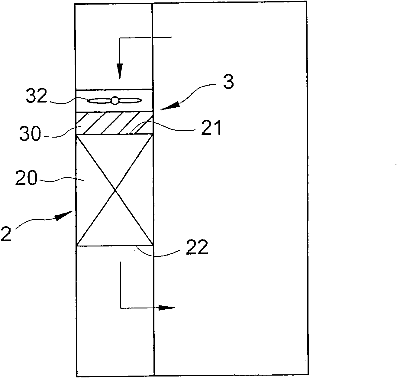
[0019] Such as image 3 As shown, it is the first preferred embodiment of the defrosting device 3 of the refrigeration system 2 of the present invention. The refrigeration system 2 has an evaporator 20 with an inlet 21 and an outlet 22 for air flow. The frosting device 3 is used to reduce the degree of frosting of the evaporator 20 and includes a dissociation unit 30 and a fan unit 32 .

[0020] The dissociation unit 30 is arranged at the entrance 21 of the evaporator 20 and is used to dissociate the water molecules in the air. The fan unit 32 is spaced from the dissociation unit 30 and is arranged adjacent to the evaporator 20 Inlet 21 , and the dissoc...


PUM


Abstract

The invention relates to a defrosting-free device of a freezing system. The freezing system is provided with an evaporator which is provided with an inlet and an outlet for air to flow. The defrosting-free device comprises a dissociation unit and a fan unit, wherein the dissociation unit is adjacent to the inlet of the evaporator and is used for dissociating water molecules in the air; and the fan unit and the dissociation unit are arranged at intervals to ensure that the dissociated water molecules can be blown away. In the invention, the water molecules in the area at the inlet of the evaporator are dissociated into the nanometer level through the dissociation unit so that frost ice crystals on the evaporator are very fine, and the frost ice crystals are blown away by the fan unit so as to greatly reduce the frost on the evaporator. The invention can not only effectively avoid subsequent defrosting operation, but also can save the time and the electric quantity consumed for the defrosting operation.

Description

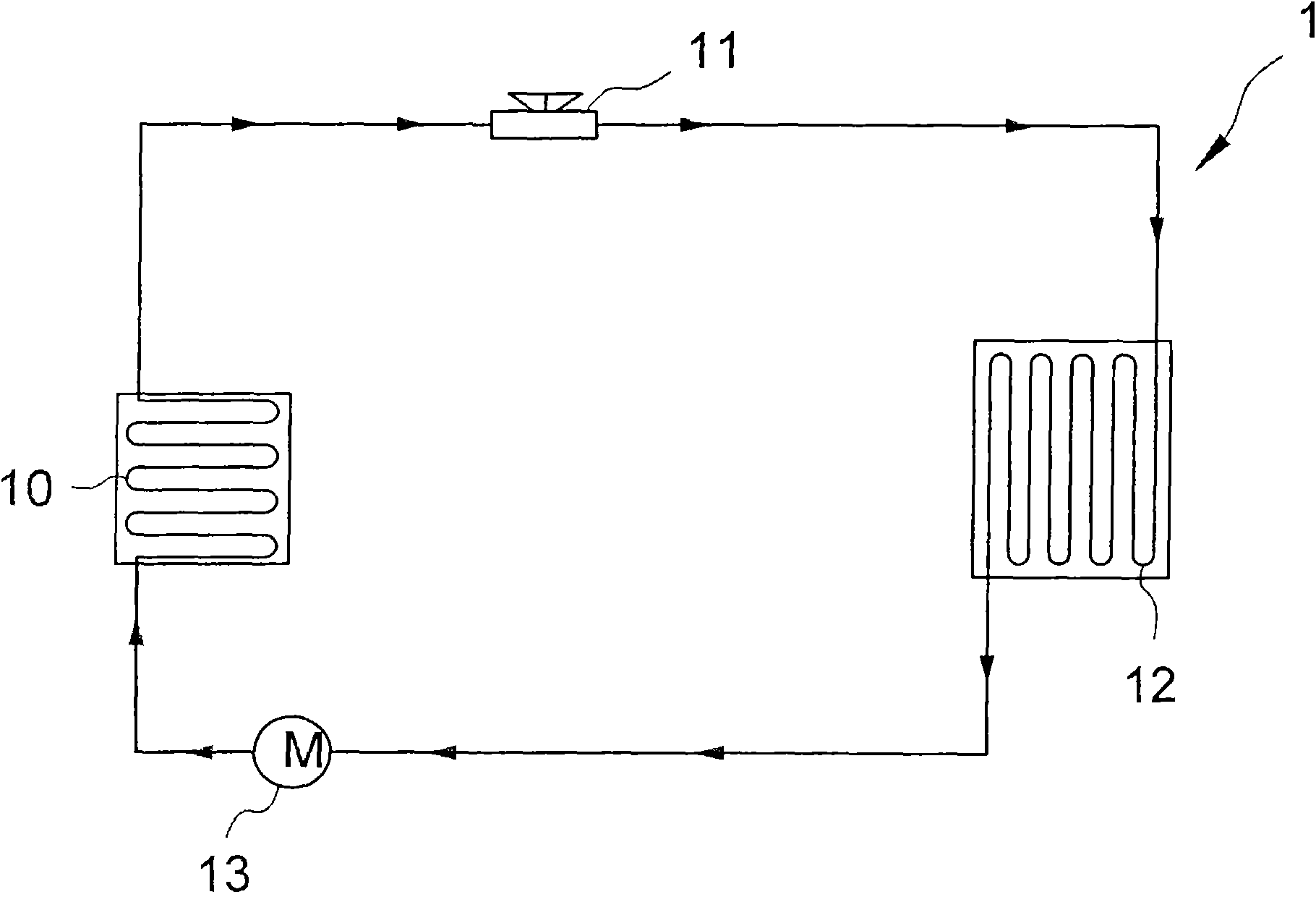
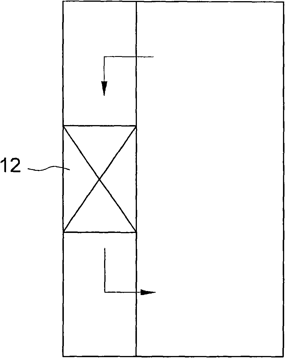
technical field [0001] The invention relates to a defrosting device, in particular to a defrosting device for a refrigeration system. Background technique [0002] refer to figure 1 , the existing refrigeration system is mainly heat exchange technology, through the cooperation of the condenser 10, the expansion valve 11, the evaporator 12, and the compressor 13, and the conversion of the refrigerant (as shown by the arrow) between the liquid state and the gaseous state, so as to Absorb and release a lot of heat. [0003] refer to figure 2 , the cold air circulates in and out of the evaporator 12 (as shown by the arrow), because the air is rich in water molecules, causing the evaporator 12 to begin to accumulate frost due to the temperature cooling, this frost will not only occupy space and affect heat exchange In addition to the work of the evaporator 12, the air passage of the evaporator 12 cannot be exchanged with the air in a large amount. Therefore, the refrigeration...

Claims


Application Information

Patent Timeline
Patent Type & Authority Applications(China)
IPC IPC(8): F25B47/02F25B39/02
Inventor 柯茂全
Owner 柯茂全
Learn More