

Refrigerator
A technology for refrigerators and air conditioners, applied in the field of refrigerators, can solve problems such as rising costs, and achieve the effects of reducing the influence of temperature, improving flow, and inhibiting the deterioration of freshness
- Summary
- Abstract
- Description
- Claims
- Application Information
AI Technical Summary
Problems solved by technology
Method used
Image

Examples
no. 1 approach
[0072] Hereinafter, embodiments of the present invention will be described in detail using the drawings.
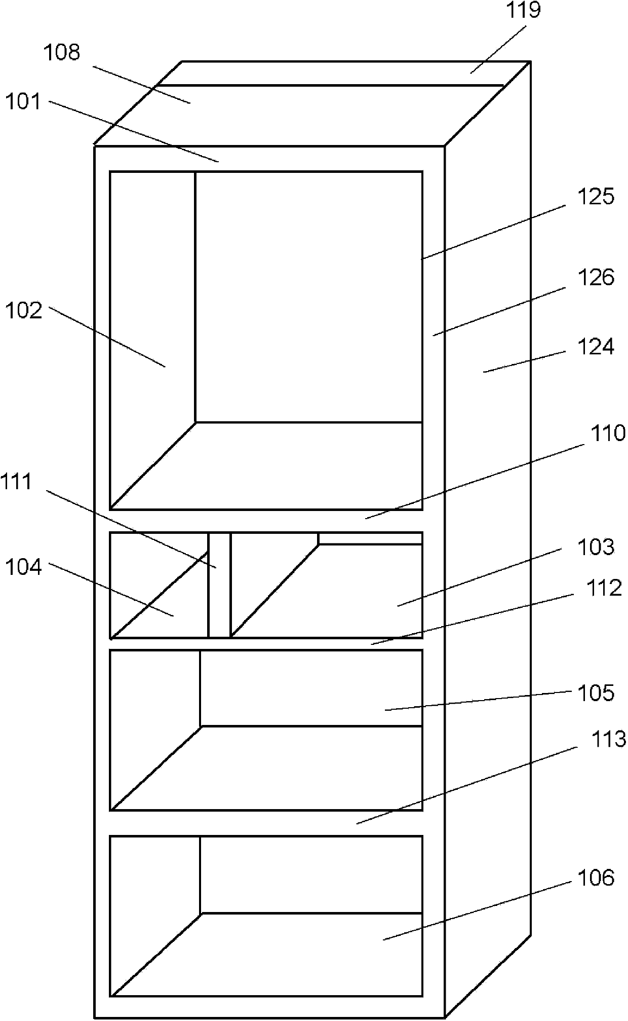
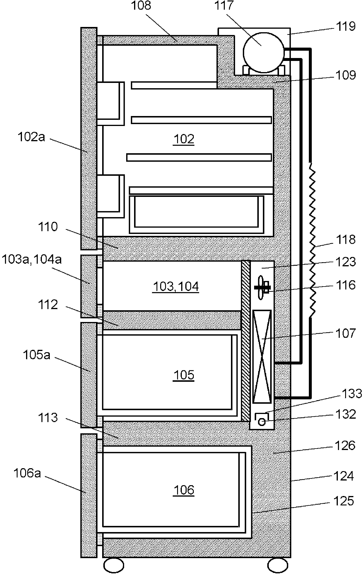
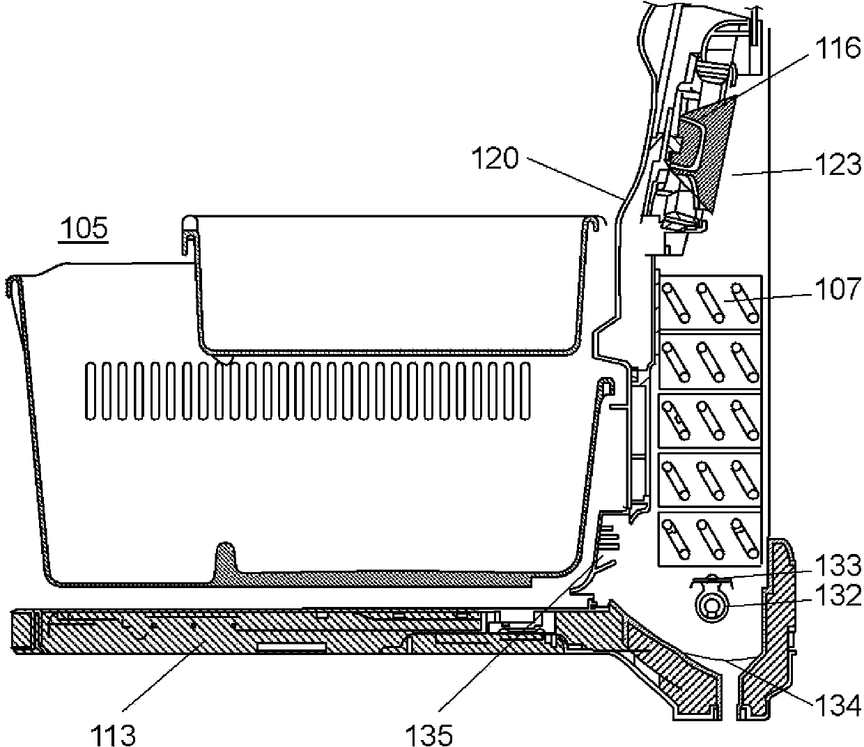
[0073] figure 1 It is a perspective view of the refrigerator which concerns on 1st Embodiment of this invention. figure 2 It is a longitudinal sectional view of the refrigerator of 1st Embodiment of this invention. image 3 It is a vertical cross-sectional view of the periphery of the cooler of the refrigerator according to the first embodiment of the present invention. Figure 4 It is a vertical cross-sectional detailed view of the periphery of the cooler of the refrigerator according to the first embodiment of the present invention.
[0074] Such as Figure 1 to Figure 4 As shown, the refrigerator main body 101 has a metal (for example, iron plate) outer case 124 opening at the front, a hard resin (for example, ABS) inner case 125 , and a foam-filled outer case 124 and inner case. The heat insulation main body 126 that the rigid polyurethane foam between 125 const...
no. 2 approach
[0127] Figure 6 It is a vertical cross-sectional detailed view of the periphery of the cooler of the refrigerator according to the second embodiment of the present invention.
[0128] Such as Figure 6 As shown, there is a cooler 157 installed on the back of the main body of the refrigerator to generate cold air; and a defrosting heater 182 provided under the cooler 157 and constituted by a glass tube heater. Below the defrosting heater 182 is provided a drain pan 184 integrally formed with the lower surface of the freezer compartment to receive defrosting water that melts and falls adhering to the cooler 157 . A cool air return port 185 for returning the cool air that cooled freezer compartment 155 to cooler 157 is provided at a lower portion of cooler cover 170 that covers cooler 157 . The center of defrosting heater 182 is arranged above the upper surface of fourth heat insulating partition 163 on the lower surface of freezing compartment 155 .
[0129]In this Embodimen...
no. 3 approach
[0131] Figure 7 It is a vertical cross-sectional detailed view of the periphery of the cooler of the refrigerator according to the third embodiment of the present invention.
[0132] Such as Figure 7 As shown, there is a cooler 207 installed on the back of the main body of the refrigerator to generate cold air; and a defrosting heater 232 provided under the cooler 207 and composed of a glass tube heater. Below the defrosting heater 232 is provided a drain pan 234 integrally formed with the lower surface of the freezer compartment to receive defrosting water falling from the melting of the frost adhering to the cooler 207 . A cool air return port 235 for returning the cool air that cooled freezer compartment 205 to cooler 207 is provided at a lower portion of cooler cover 220 that covers cooler 207 . The wind direction guide 222 is provided at the cold air return port 235 , and the center of the defrosting heater 232 is arranged above the upper surface of the fourth heat in...
PUM
 Abstract
Description
Claims
Application Information