Stapling head of non-closed surgical stapling machine

A closed-loop, device-based technology, applied in the field of medical devices, can solve problems such as fracture nail line coverage, hidden dangers of patients' operations, incomplete closure of broken ends, etc., and achieve the effect of eliminating hidden dangers of incomplete closure

Inactive Publication Date: 2009-12-09
TOUCHSTONE INTERNATIONAL MEDICAL SCIENCE CO LTD
View PDF0 Cites 1 Cited by
  • Summary
  • Abstract
  • Description
  • Claims
  • Application Information

AI Technical Summary

Problems solved by technology

In the existing non-closed-loop surgical binding instruments, the fracture cannot be guaranteed to be completely covered by the staple line, and incomplete closure of the broken end may occur during the binding process, which brings hidden dangers to the patient's operation

Method used


Image

  • Stapling head of non-closed surgical stapling machine
  • Stapling head of non-closed surgical stapling machine
  • Stapling head of non-closed surgical stapling machine

Examples


Embodiment 1

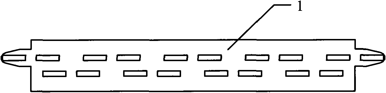
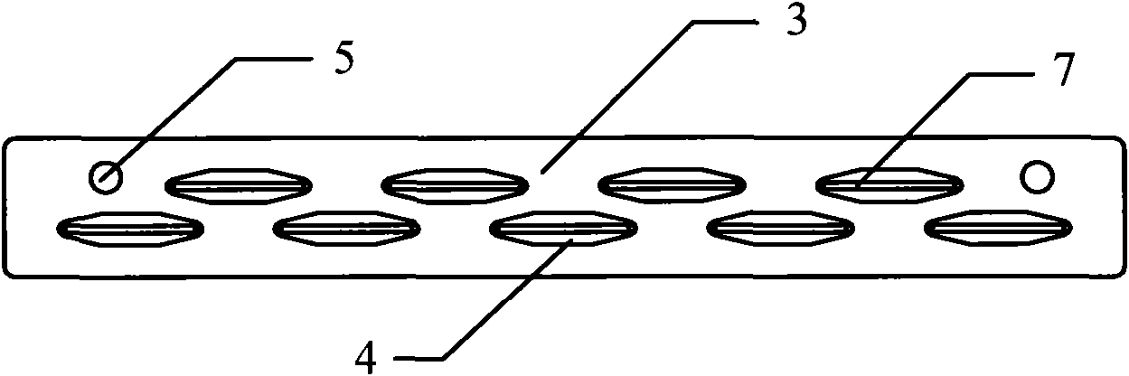
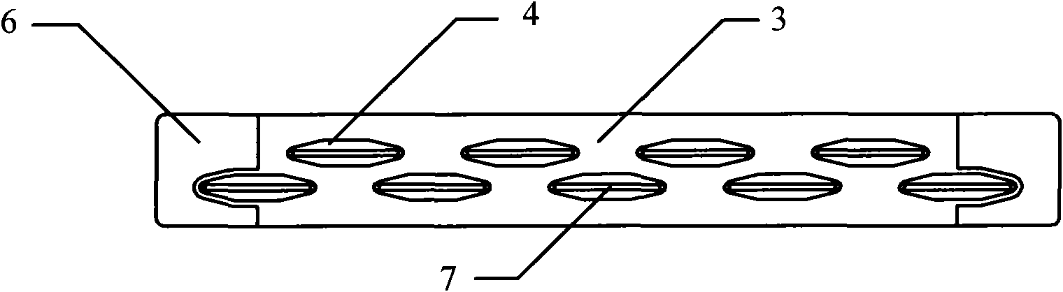
[0025] Both ends of the nailing line are provided with a limit device, which is a limit rod 6. The assembly process of the present invention is roughly as follows: firstly, the limiting rod 6 is passed through the limiting hole 5 on the staple cartridge 3 , so that the limiting rod 6 is combined with the staple cartridge 3 . Then, the staple cartridge 3 is installed on the far end of the staple pusher 2, and at the same time, the proximal end of the staple pusher 2 is installed on the binding instrument, and the limit rod 6 is connected with the corresponding control structure of the binding instrument. Next, the anvil 1 is installed on the anvil shaft, and the anvil shaft is connected to the binding instrument. Finally, it is enough to place the staples 7 in the staple cartridge holes 4 .

[0026] During the operation: first place the tissue 8 between the anvil 1 and the staple cartridge 3 , and then close the limiting rod 6 so that the tissue 8 is limited between the limiti...

Embodiment 2

[0029] Both ends of the nailing line are provided with limit devices, which are limit blocks. During manufacture, the limit block and the staple cartridge 3 can be integrally cast. The assembly process of the present invention is roughly as follows: first, the staple cartridge 3 is installed on the far end of the staple pusher 2, and then the proximal end of the staple pusher 2 is installed on the binding instrument. Next, the anvil 1 is installed on the anvil shaft, and the anvil shaft is connected to the binding instrument. Finally, place staples 7 in the staple bin holes 4 and get final product. Its usage is the same as that in Embodiment 1, and will not be repeated here.

[0030] It can be seen from the above text description and in conjunction with the accompanying drawings that after the present invention is adopted, the length of contact between the broken end of the tissue 8 and the surface of the staple cartridge can be completely covered by the nail, so that after ...


PUM


Abstract

The invention relates to a stapling head of a non-closed surgical stapling machine, belonging to the technical field of medical appliances and comprising a staple anvil, a staple pushing device and a staple chamber, wherein the staple anvil and the staple chamber are opposite to form a stapling area; at least one row of staple chamber holes is distributed on the staple chamber in linear parallelism to form a staple line; a plurality of pairs of staple grooving are distributed on the staple anvil; and the staple chamber is arranged at a far end of the staple pushing device. The stapling head is characterized in that the length of the staple line is larger than the contact length of tissues and a staple chamber surface, thereby ensuring that the broken ends of the tissues are completely closed after being stapled by the stapling machine.

Description

technical field [0001] The invention relates to a binding head, in particular to a non-closed-loop surgical binding instrument binding head, which belongs to the technical field of medical instruments. Background technique [0002] Surgical binding instruments are widely used in digestive tract reconstruction surgery, because of its short operation time and good suture effect, it has gradually replaced manual suture. Furthermore, the surgical binding instrument adopts the principle of a stapler. There are staples placed in a circular or other shaped staple cartridge, and behind the staple cartridge is a pusher piece. The staples are pushed out, and after the staples have pierced through the tissue, they will abut against the anvil. The staples are finally formed into a "B", and the staple forming slots are arranged in pairs, corresponding to the staple cartridges. [0003] According to the shape of the suture opening, surgical stapling instruments can be simply divided int...

Claims


Application Information

Patent Timeline
Patent Type & Authority Applications(China)
IPC IPC(8): A61B17/072
Inventor 陈望东丁水澄
Owner TOUCHSTONE INTERNATIONAL MEDICAL SCIENCE CO LTD
Why Eureka
Try Eureka