
Storage system, storage controller, and cache implementing method in the storage system

A storage controller and storage system technology, applied in storage systems, instruments, memory address/allocation/relocation, etc., can solve the problems of reducing storage system performance, not improving storage system performance, unable to read and write data cache, etc. The effect of improving the performance of the storage system

Inactive Publication Date: 2009-07-29
NEW H3C TECH CO LTD
View PDF0 Cites 21 Cited by
  • Summary
  • Abstract
  • Description
  • Claims
  • Application Information

AI Technical Summary

Problems solved by technology

[0014] 2. Cache and RAID compete for resources: Cache and RAID share the same RAID controller and FC / iSCSI data path, which will cause competition for resources, thereby reducing the performance of the storage system
[0015] 3. There are hidden dangers in data security
If there are multiple disk cabinets in the system, when the disk cabinet where the member disk used as the cache is located is powered off, the data in the cache will be lost, and the read and write data of the RAID in other disk cabinets cannot be cached, thereby reducing the storage system capacity. performance
[0016] It can be seen that the purpose of cache expansion is to improve the performance of the storage system, and the existing scheme of using the member disks in RAID as cache to achieve cache expansion will lead to various problems that reduce the performance of the storage system, so this scheme does not Improving the performance of storage system through cache expansion

Method used


Image

  • Storage system, storage controller, and cache implementing method in the storage system
  • Storage system, storage controller, and cache implementing method in the storage system
  • Storage system, storage controller, and cache implementing method in the storage system

Examples


Embodiment Construction

[0048] In order to make the object, technical solution and advantages of the present invention clearer, the present invention will be further described in detail below with reference to the accompanying drawings and examples.

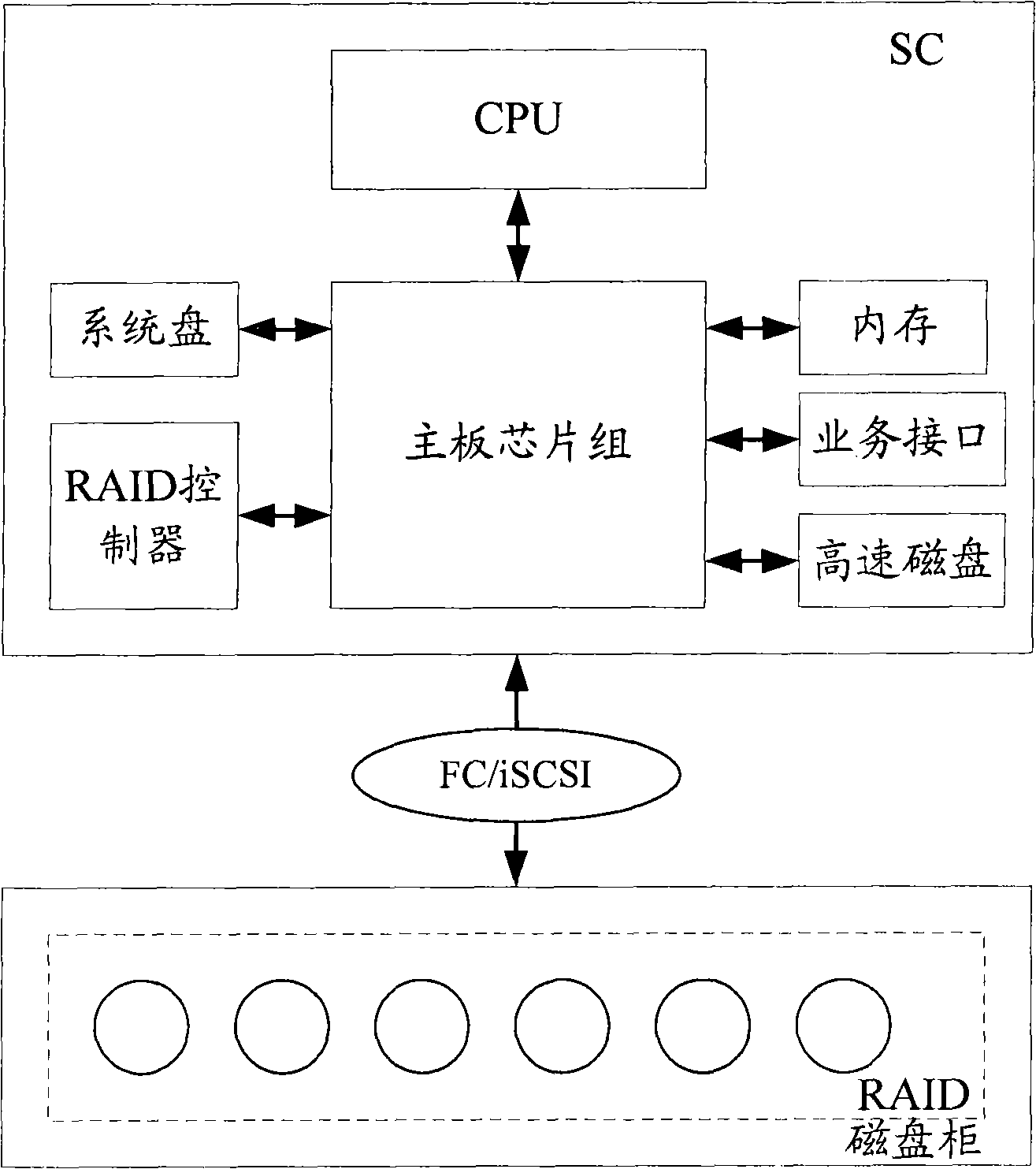
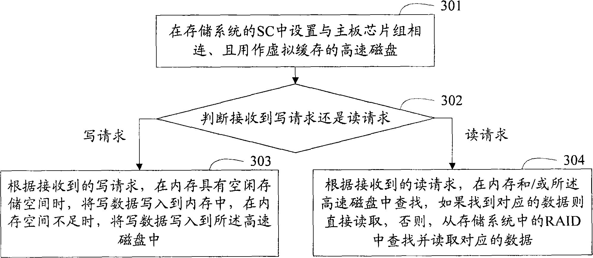
[0049] In the present invention, a high-speed disk is arranged inside the SC, and the high-speed disk is used as a virtual cache, so that the cache capacity can be infinitely expanded by increasing the capacity of the high-speed disk and the size of the configured virtual cache.

[0050] In this way, in the existing solution of using the member disks in the RAID as a cache to achieve cache expansion, the problem that the data passes repeatedly during the process of reading and writing the cache will cause a large overhead of the FC / iSCSI data path will not occur, nor will it The problem of cache and RAID competing for resources occurs, and the hidden dangers of data security can also be eliminated. That is to say, the present invention can avoid various...


PUM


Abstract

The invention discloses a storage system. The interior of a storage controller (SC) is provided with a high-speed disk which is used as a virtual buffer memory, so that the buffer memory capacity can be infinitely expanded through increasing the capacity of the high-speed disk and the size of the equipped virtual buffer memory; therefore, the capacity of the buffer memory can be flexibly expanded without the limits of system hardware; and simultaneously the problem of large cost of data paths caused by repeated data reading and writing during the process of reading and writing the buffer can not appear, the problem of competing resources of the buffer memory with a disk array in a disk cabinet can not appear, and the potential troubles of data safety can be eliminated. That is to say, the invention can realize the capacity expansion of the buffer memory and meanwhile, can avoid the problems with probability of resulting in lowering the performance of the storage system in the existing scheme, and therefore, the performance of the storage system can be improved by the capacity expansion of the buffer memory. The invention further discloses an SC in the storage system and a buffer memory realizing method in the storage system.

Description

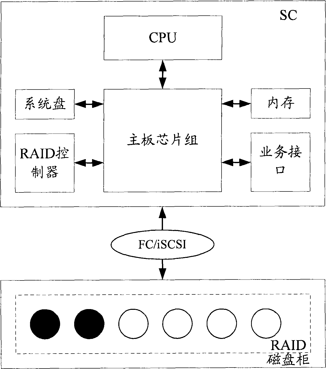
technical field [0001] The present invention relates to cache technology, and in particular to a storage system, a storage controller (Storage Controller, SC) in the storage system, and a cache implementation method in the storage system. Background technique [0002] A storage system for providing services to network hosts usually consists of two parts, an SC and a disk cabinet, wherein a redundant array of independent disks (Redundant Array of Independent Disks, RAID) composed of multiple member disks is set in the disk cabinet. [0003] figure 1 It is a schematic diagram of the structure of the current storage system. Such as figure 1 As shown, the SC is connected to the disk enclosure through the Internet Small Computer System Interface (iSCSI) or the Fiber Channel (Fibre Channel, FC) interface. The SC in the storage system includes: the mainboard chipset (Chip Set), and the The chipset is connected to the central processing unit (CPU), RAID controller, system disk, a...

Claims


Application Information

Patent Timeline
Patent Type & Authority Applications(China)
IPC IPC(8): G06F12/08G06F12/0871
Inventor 胡微上官应兰
Owner NEW H3C TECH CO LTD
Learn More