Electric dust collector
A vacuum cleaner and electric technology, which is applied in the installation of vacuum cleaners, vacuum cleaner equipment, electrical equipment, etc., to achieve the effect of reducing the burden on hands and improving the degree of freedom of use
- Summary
- Abstract
- Description
- Claims
- Application Information
AI Technical Summary
Problems solved by technology
Method used
Image

Examples
Example Embodiment
[0037] (Example 1)
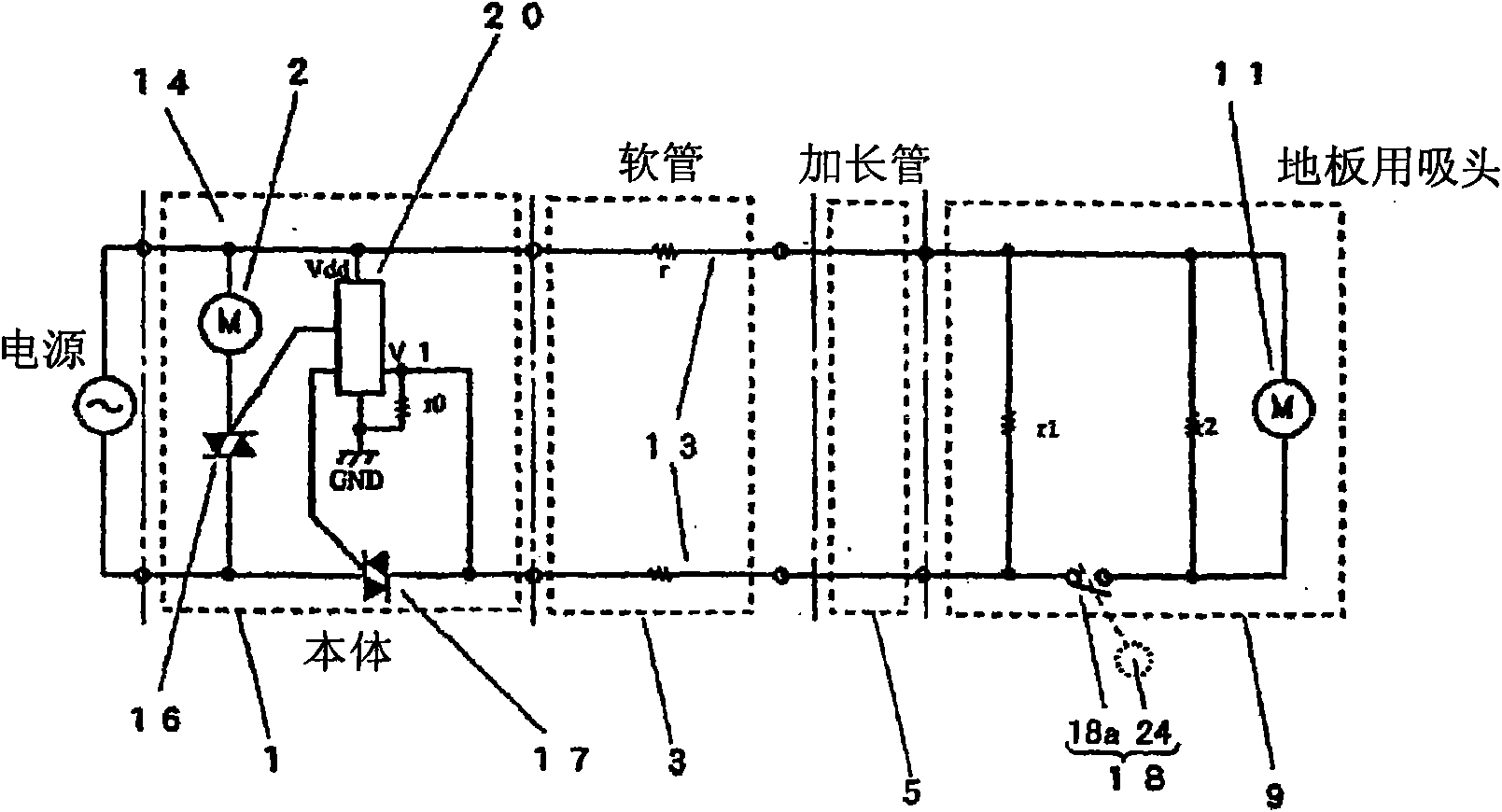
[0038] figure 1 The circuit structure of the electric vacuum cleaner of the first embodiment of the present invention is shown. For the sake of brevity, the same components as those in the above-mentioned existing electric vacuum cleaner are marked with the same symbols here, and detailed descriptions thereof are omitted.
[0039] in figure 1 Among them, 9 is a suction head for sucking dust from the cleaning surface, and the example here is a suction head for the floor. The suction head 9 for the floor is installed on the extension pipe 5 in a freely detachable manner. A rotating brush 10 and a motor 11 for driving the rotating brush 10 are installed inside the suction head 9 for the floor. The electric motor 11 relies on a power cord 13 provided on the suction channel for power supply.
[0040] The main body 1 of the vacuum cleaner is equipped with an electric fan 2 for generating a dust suction airflow and a dust collecting chamber 6 for collecting dust. ...
Example Embodiment
[0101] (Example 2)
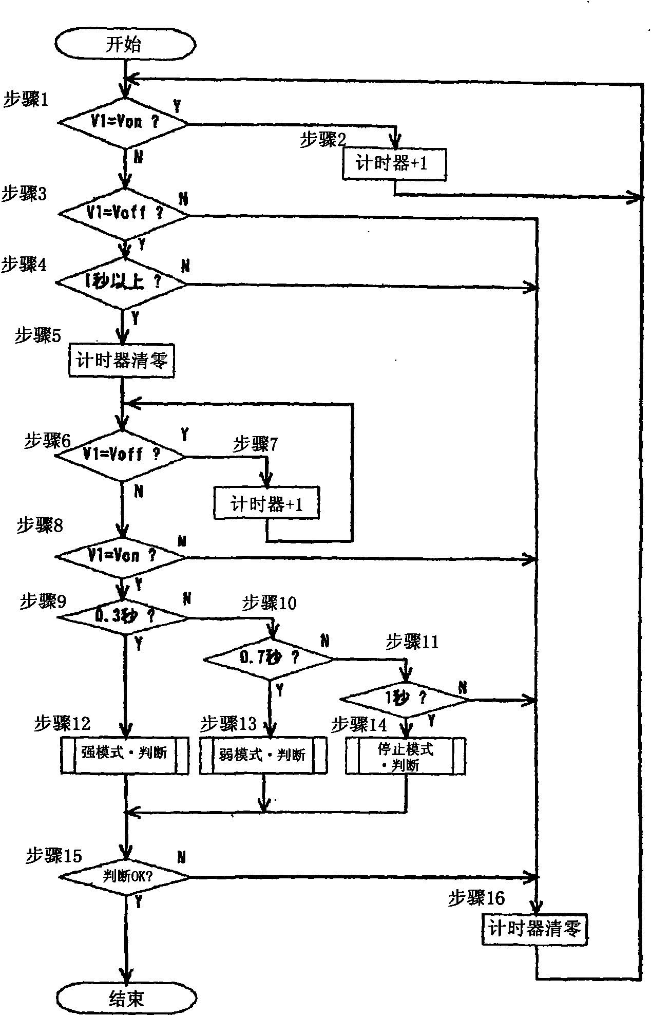
[0102] Figure 7 It is a flowchart of the mode conversion determination of the electric vacuum cleaner of the second embodiment of the present invention, Figure 8 It shows a flowchart for determining the strong / weak mode of the vacuum cleaner. In addition, the same components as those of the electric vacuum cleaner of the prior art and the first embodiment described above are denoted by the same reference numerals, and descriptions thereof will be omitted.
[0103] In the actual implementation form this time, the difference from the above-mentioned first embodiment is that the mode conversion determination process set in the microcomputer 20 in advance, as shown in Table 2, the strength mode is the same, and the mode is determined every time The mode 1 of the conversion process is input into V1, and the strong mode and the weak mode are converted in order.
[0104]
[0105]
[0106] For the conversion of the strong mode and the weak mode and the mode conv...
Example Embodiment
[0118] (Example 3)
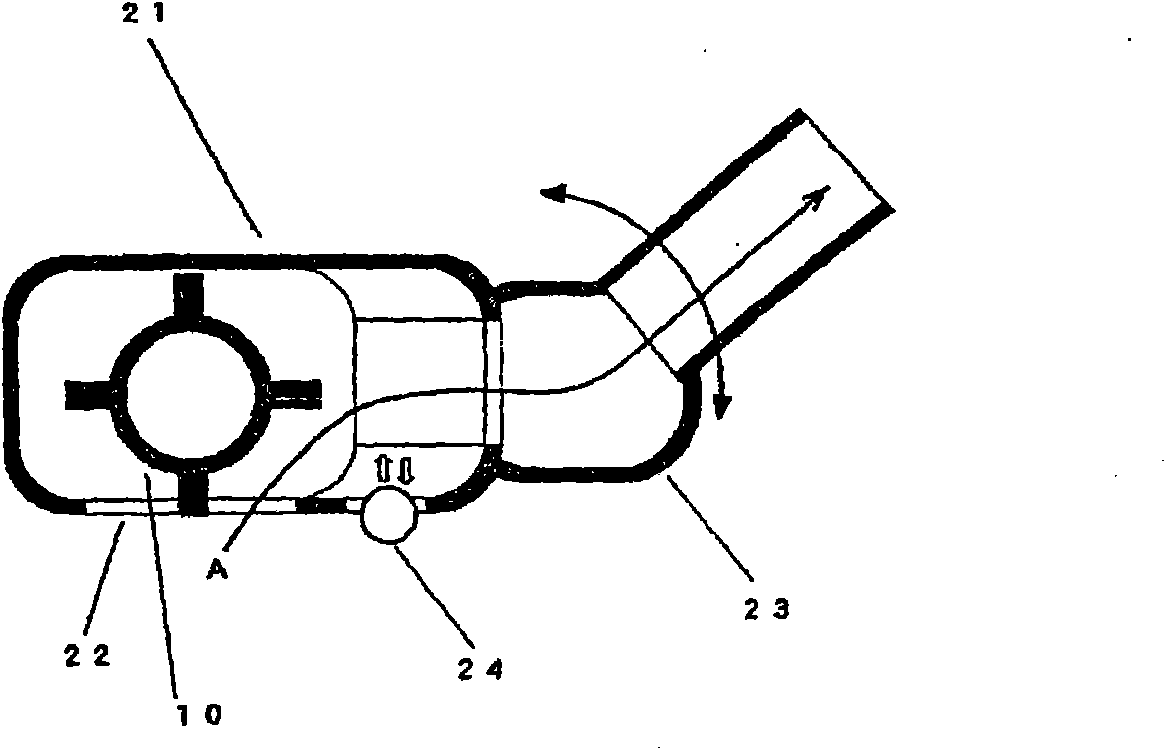
[0119] Picture 9 It is an operation explanatory diagram of the suction head for the floor of the electric vacuum cleaner according to the third embodiment of the present invention. In addition, the same components as those of the conventional electric vacuum cleaner and the electric vacuum cleaner of the above-mentioned embodiment are denoted by the same reference numerals, and the description is omitted.
[0120] in Picture 9 Among them, the difference from the above-mentioned first embodiment is that the roller 24 is arranged at the front of the suction head main body 21.
[0121] Next, the operation of the electric vacuum cleaner of this embodiment will be described.
[0122] When the user is cleaning while holding the handle 8 or the extension tube 5, the suction head 9 for the floor moves back and forth on the floor. At this time, if cleaning is performed on a floor with a height difference or a carpet, depending on the type of the carpet, the suction he...
PUM
 Abstract
Description
Claims
Application Information
 - R&D
- Intellectual Property
- Life Sciences
- Materials
- Tech Scout
- Unparalleled Data Quality
- Higher Quality Content
- 60% Fewer Hallucinations
Browse by: Latest US Patents, China's latest patents, Technical Efficacy Thesaurus, Application Domain, Technology Topic, Popular Technical Reports.
© 2025 PatSnap. All rights reserved.Legal|Privacy policy|Modern Slavery Act Transparency Statement|Sitemap|About US| Contact US: help@patsnap.com