
High flow piezoelectric pump

A piezoelectric pump, piezoelectric material technology, applied in the direction of pumps, pumps with flexible working elements, liquid variable capacity machines, etc., can solve problems such as the inability to provide high fluid flow in the hydraulic control system of the transmission

Inactive Publication Date: 2009-12-23
GM GLOBAL TECH OPERATIONS LLC
View PDF5 Cites 30 Cited by
  • Summary
  • Abstract
  • Description
  • Claims
  • Application Information

AI Technical Summary

Problems solved by technology

However, conventional piezoelectric pumps cannot provide the high fluid flow required by transmission hydraulic control systems

Method used


Image

  • High flow piezoelectric pump
  • High flow piezoelectric pump

Examples


Embodiment Construction

[0018] The following description is merely exemplary in nature and is not intended to limit the application, application or use.

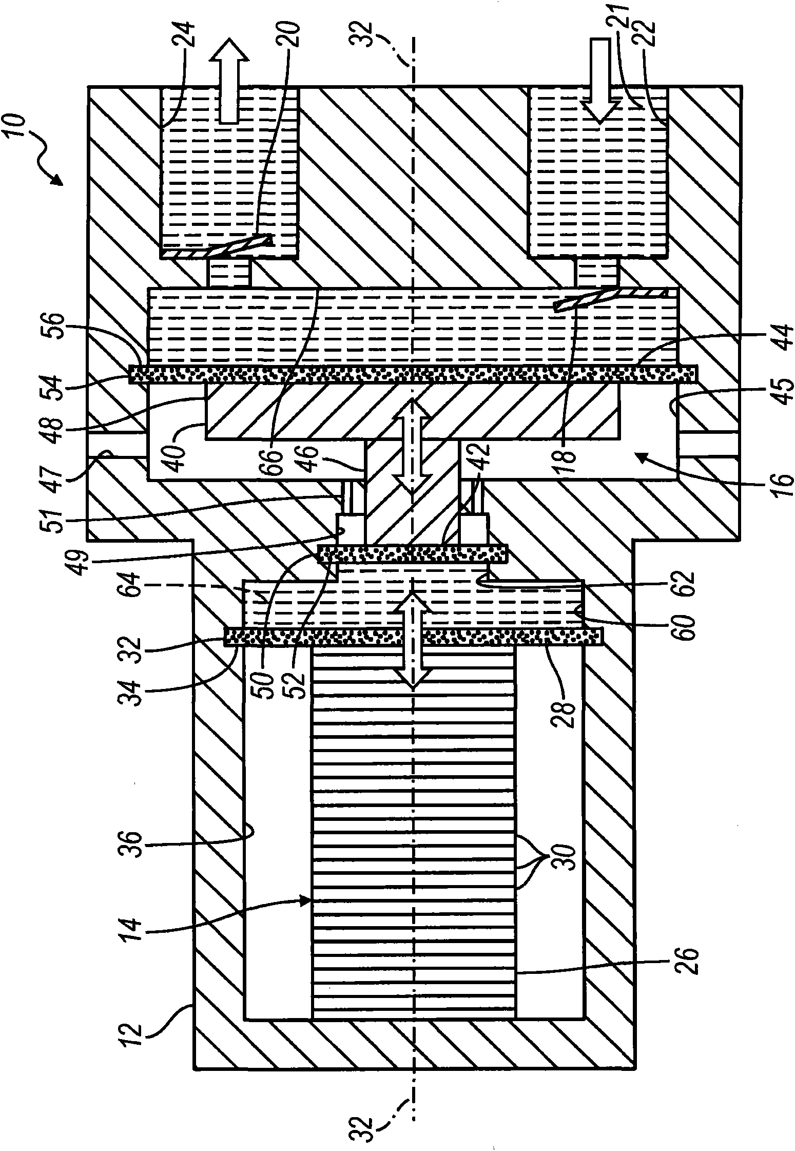
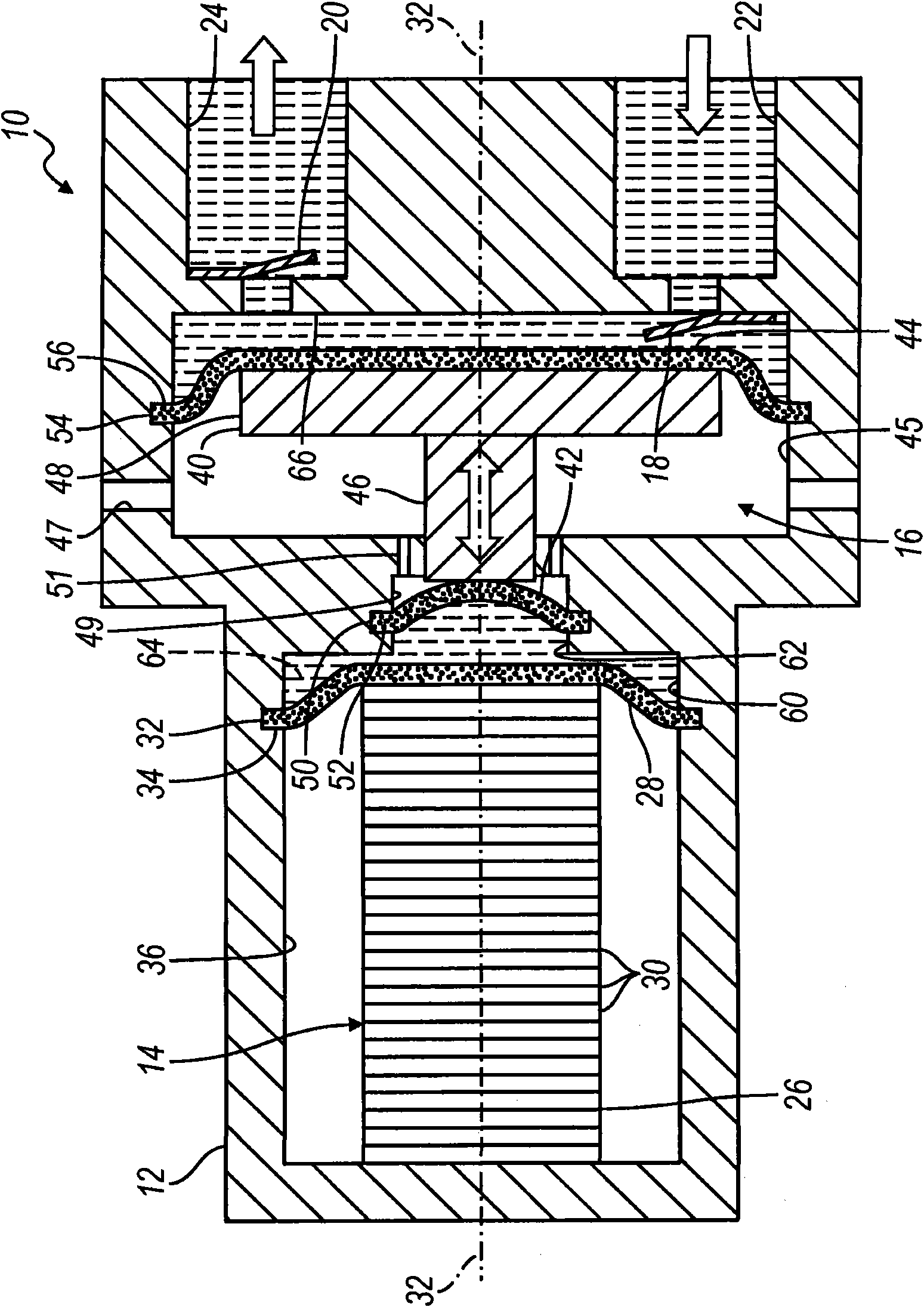
[0019] Referring to FIG. 1 , a piezoelectric pump in accordance with the principles of the present invention is generally indicated by the reference numeral 10 . The pump 10 generally includes a pump housing 12 , an actuator assembly 14 , a piston assembly 16 , an inlet valve 18 and an outlet valve 20 . As will be described in detail below, the pump 10 is operable to pump a substance, such as hydraulic fluid 21 , through an inlet 22 in the housing 12 to an outlet 24 in the housing 12 .

[0020] The actuator assembly 14 is located within the housing 12 and includes an actuator stack 26 in at least partial contact with a first diaphragm 28 . The actuator stack 26 is composed of a plurality of stacked layers 30 of piezoelectric material. Layer 30 of piezoelectric material is comprised of a piezoelectric material operable to expand and contract (ie, ...


PUM


Abstract

The present invention relates to a high flow piezoelectric pump. A piezoelectric pump for pumping a fluid at a high flow rate includes a housing and an actuator located within the housing. An electric voltage applied to the actuator causes the actuator to apply a force to a first diaphragm that is proximate to the actuator. A piston assembly is located within the housing and is moveable between at least a first position and a second position. A first fluid chamber is defined by the housing, the first diaphragm, and the piston assembly. A coupling fluid is located within the first fluid chamber for coupling the first diaphragm to the piston assembly. A second fluid chamber is defined by the housing and the piston assembly. An inlet valve is in communication with the second fluid chamber and an outlet valve is in communication with the second fluid chamber.

Description

technical field [0001] The present application relates to a piezoelectric pump, and in particular to a piezoelectric pump having a fluid coupling (hydraulic coupling) between a piezoelectric actuator and a piston, capable of providing a high flow rate of hydraulic fluid. Background technique [0002] The statements in this section merely provide background information related to the present application and may or may not constitute prior art. [0003] A typical piezoelectric pump includes a stack of piezoelectric actuators located within the pump housing. The piezoelectric stack is composed of a piezoelectric material that, when a voltage is applied thereto, expands and contracts in shape and / or size as compared to its normal state when no voltage is applied. The actuator stack is operable to engage a diaphragm located within the fluid chamber. The fluid chamber communicates with a one-way inlet valve and a one-way outlet valve. When a voltage is applied to the actuator s...

Claims


Application Information

Patent Timeline
Patent Type & Authority Applications(China)
IPC IPC(8): F04B43/04
CPCF04B43/067F04B43/046F04B17/003F04B43/04
Inventor S·白J·C·舒尔茨V·A·尼拉肯坦
Owner GM GLOBAL TECH OPERATIONS LLC
Learn More