Thin-film magnetic head for microwave assist and microwave-assisted magnetic recording method

A thin-film magnetic head and magnetic recording technology, which is applied in the direction of using thin-film magnetic heads, recording/reproduction/deletion methods, magnetic recording, etc., can solve the problem that any influence of frequency is not considered, and achieve the effect of excellent microwave-assisted magnetic recording

Inactive Publication Date: 2009-12-23
TDK CORPARATION
View PDF2 Cites 7 Cited by
  • Summary
  • Abstract
  • Description
  • Claims
  • Application Information

AI Technical Summary

Problems solved by technology

However, any effect on the frequency caused by the write field received by the spin wave excitation element from the main pole is completely disregarded

Method used


Image

  • Thin-film magnetic head for microwave assist and microwave-assisted magnetic recording method
  • Thin-film magnetic head for microwave assist and microwave-assisted magnetic recording method
  • Thin-film magnetic head for microwave assist and microwave-assisted magnetic recording method

Examples


Embodiment 1

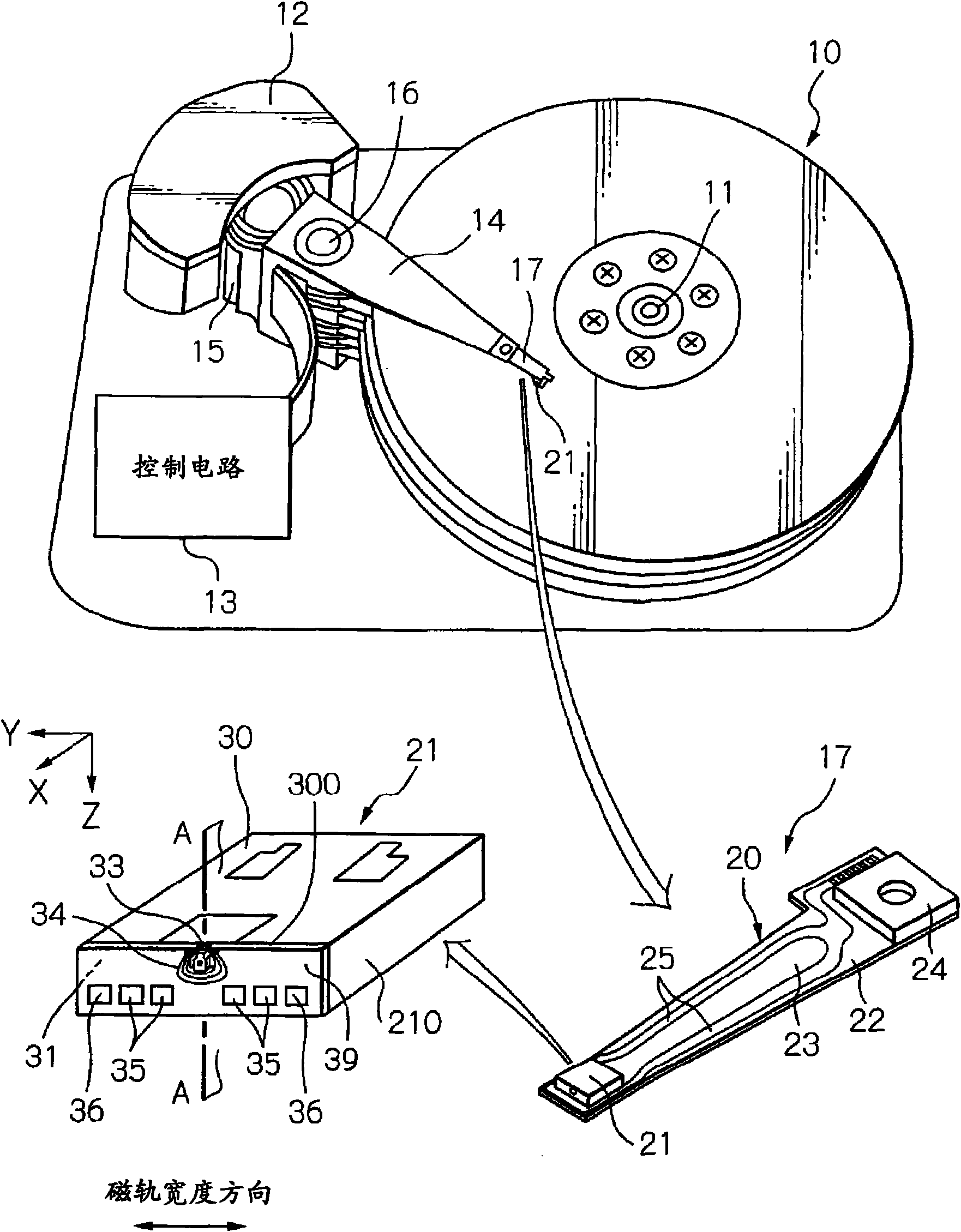
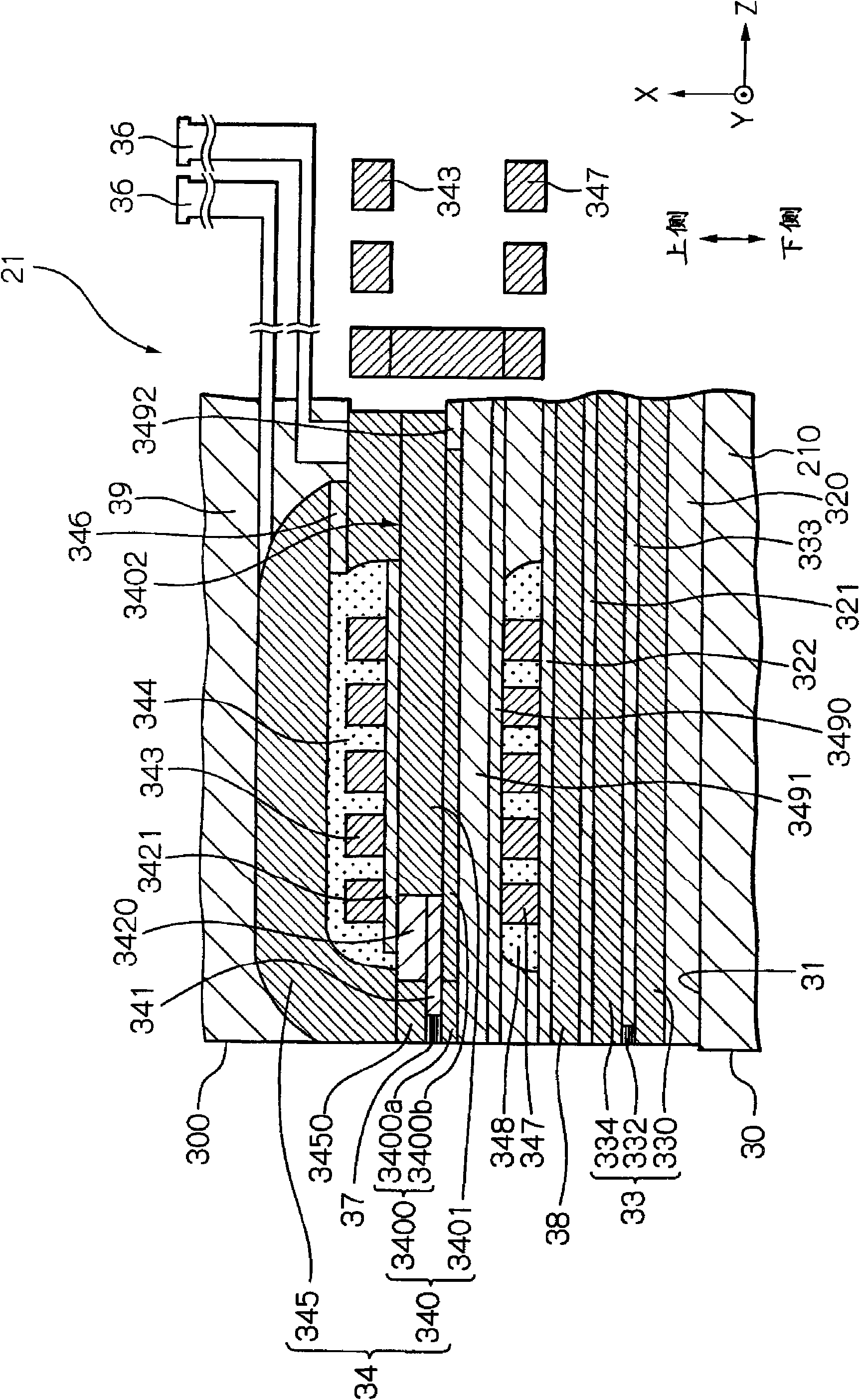
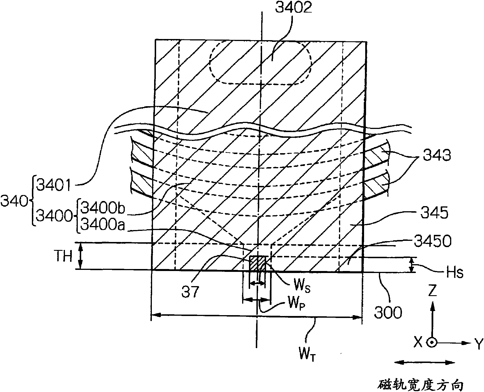
[0109] Table 1 shows the electromagnetic field generating element 37 ( Figure 4 )Configuration.

[0110] Table 1

[0111]

[0112] In Table 1, the layer surface of the layer surface region forms a YZ-plane. Each layer of the electromagnetic field generating element 37 is formed by using a sputtering method; sequentially stacked from the formed main pole front end 3400a are the base layer 370, the spin wave excitation layer 371, the nonmagnetic intermediate layer 372, the magnetization free layer 373 and the protective Layer 374. During the deposition of the spin wave excitation layer 371 and the magnetization free layer 373, by applying a magnetic field of 50 Oe perpendicular to the layer surface, an induced magnetic anisotropy with a direction perpendicular to the layer surface was obtained. Therefore, in the manufacturing including the formed electromagnetic field generating element 37 and the MR element 33 and the electromagnetic transducer 34 ( figure 2 and Figur...

Embodiment 2

[0115] Table 2 shows the electromagnetic field generating element 70 ( Figure 7a )Configuration.

[0116] Table 2

[0117]

[0118] In Table 2, the layer surface of the layer surface region forms a YZ-plane. Each layer of the electromagnetic field generating element 70 is formed by using a sputtering method; sequentially stacked from the formed main pole tip 3400a are the base layer 700, the spin wave excitation layer 701, and the nonmagnetic intermediate layer 702. By applying a magnetic field of 50 Oe perpendicular to the layer surface during deposition of the spin wave excitation layer 701 , an induced magnetic anisotropy with a direction perpendicular to the layer surface is obtained. Therefore, manufacturing includes the formed electromagnetic field generating element 70 and the MR element 33 and the electromagnetic transducer 34 ( figure 2 and Figure 3a , 3b ) after the thin-film magnetic head 21, start to operate the electromagnetic transducer 34, and adjust t...


PUM

PropertyMeasurementUnit
thicknessaaaaaaaaaa
thicknessaaaaaaaaaa
thicknessaaaaaaaaaa

Abstract

Provided is a thin-film magnetic head that can stably generate electromagnetic field with a desired frequency, even under the existence of significantly strong write field with frequently reversed direction. The head comprises an electromagnetic-field generating element between the first and second magnetic poles. The electromagnetic-field generating element comprises a spin-wave excitation layer provided adjacent to the first magnetic pole and having a magnetization with its direction varied according to external magnetic fields, for generating an high frequency electromagnetic field by an excitation of spin wave. And a magnetization of the spin-wave excitation layer is biased in a direction substantially perpendicular to its layer surface by a portion of magnetic field generated from the first magnetic pole, and pin-wave excitation current flows in the electromagnetic-field generating element in a direction from the second pole to the first pole.

Description

technical field [0001] The present invention relates to a thin film magnetic head used in a microwave-assisted magnetic recording technique in which data is written to a part of a magnetic recording medium irradiated with microwaves, and to a magnetic recording method using the technique. Background technique [0002] In magnetic recording devices for higher recording densities, especially magnetic disk drives, the performance of thin-film magnetic heads needs to be further improved. As such a thin film magnetic head, a composite type thin film magnetic head having a stacked structure of a magnetoresistive (MR) element for reading data and an electromagnetic transducer for writing data is widely used at present. These elements perform read and write operations to a magnetic disk as a magnetic recording medium. [0003] In general, magnetic recording media are magnetically discontinuous in which magnetic particles are aggregated together. Generally, each magnetic particle h...

Claims


Application Information

Patent Timeline
Patent Type & Authority Applications(China)
IPC IPC(8): G11B5/31H01F10/08G11B5/48G11B5/02
CPCG11B5/314G11B2005/0024
Inventor 岛沢幸司长勤土屋芳弘
Owner TDK CORPARATION
Why Eureka
Try Eureka