Chain and chain wheel

A chain and special technology, applied in the direction of belt/chain/gear, chain ring, transmission chain, etc., can solve the problems of reducing the service life of chain pumping units, increasing maintenance time, affecting the efficiency of pumping operations, etc., and reaching the service life The effect of long length, high tooth surface strength and stable transmission

Inactive Publication Date: 2011-05-04
JILIN JIRUI GASOLINEEUM MACHINERY
View PDF5 Cites 0 Cited by
  • Summary
  • Abstract
  • Description
  • Claims
  • Application Information

AI Technical Summary

Problems solved by technology

When the special link of the chain drives the connecting rod to make the balance box reciprocate in a straight line in the vertical direction, the polished rod at the wellhead pulled by the traction rope connected with the balance box also makes a reciprocating motion in a straight line. The plates are all in the shape of "8", and the inner and outer chain plates are unconstrained. When the special chain link of the suspended load passes through the driving sprocket to change direction, the driving sprocket makes the chain pull through the chain link behind the driving sprocket, while the front The chain link is in a relaxed state by the thrust, and the driving sprocket is continuously rotating, but the special chain link must wait for the chain link that has moved in the opposite direction to tighten before continuing to move, resulting in a reversing impact on the load suspended by the special chain link of the chain , within a certain range, the greater the degree of slack in the transmission chain, the greater the degree of reversing impact generated by the chain pumping unit, and the continuous reversing impact will lead to faster wear between the kinematic pairs. The service life of the chain pumping unit is reduced, the maintenance time is increased, the efficiency of the pumping operation is affected, and the production cost is increased

Method used


Image

  • Chain and chain wheel
  • Chain and chain wheel
  • Chain and chain wheel

Examples


Embodiment Construction

[0031] The present invention will be described in detail below using the drawings and embodiments.

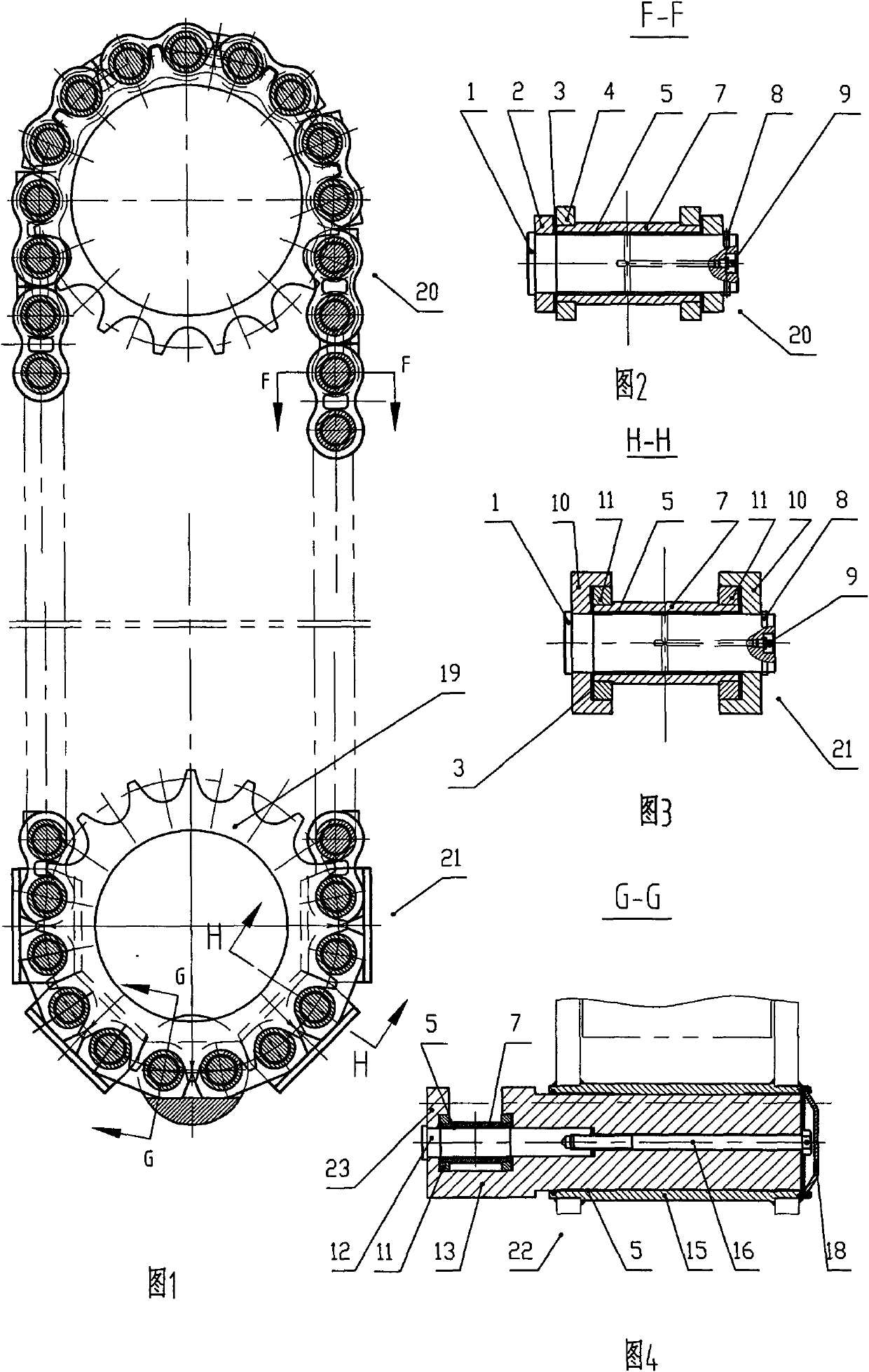
[0032] refer to figure 1 , 2 And 5-10, a chain includes several joints 20 hinged in turn, several joints 20 are existing common chains, the structure of the chains 20 is to include rollers 7, and the two ends of the rollers 7 are nested Chain plate 4, sealing ring 3 is placed on the outside of inner chain plate 4 to contact with outer chain plate 2, and is hinged by pin 1, and the shaft end of pin 1 is fixed with steel wire lock ring 8 for shaft. A composite bearing 5 is provided between the roller 7 of the chain link 20 and the pin shaft 1 . The composite bearing 5 of this embodiment adopts a three-layer composite bearing (GB293-82, Φ65×60×70). An oil cup 9 is fixedly connected to the shaft end of the bearing pin 1 . The oil cup 9 can inject lubricating oil into the composite bearing 5 .

[0033] refer to figure 1 , 3 , 4 and 11-14, several joint chain links 20 and so...


PUM


Abstract

The invention relates to a chain transmission mechanism, which is a chain and a chain wheel. The chain comprises a plurality of chain links and is characterized in that the chain also comprises a plurality of specific chain links, a plurality of chain links and a plurality of specific chain links are articulated in series, the structure of the specific chain links comprises a roller, both ends ofthe roller are sleeved with specific inner chain boards, the specific inner chain boards are positioned in the grooves of specific outer chain boards and are articulated by pin rolls, the outer end face of each specific inner chain board is provided with symmetrical inclined surfaces, the specific outer chain boards are provided with grooves, the two end surfaces of the specific outer chain boards are provided with symmetrical inclined surfaces, the chain has strong carrying capacity and smooth transmission, thus the impact of reversion of chain links suspension loads can be prevented, and the service life is long. The chain wheel is characterized in that the chain wheel comprises a wheel disc, wear layers are attached on the surfaces of a plurality of chain teeth which are fixed on the wheel disc by a position pin and a fixed bolt, the tooth surface strength of the chain wheel is high, the wear resistance is good, the chain tooth can be replaced easily, and the service life is long, therefore the chain wheel is particularly applicable to the utilization in the transmission of chain suspension loads.

Description

technical field [0001] The invention relates to a mechanical transmission mechanism, which is a chain transmission mechanism, more specifically, a chain suitable for hanging loads and a sprocket wheel for driving the chain. Background technique [0002] Existing chains are formed by connecting links of several links. The chain link is composed of a roller, an inner chain plate nested at both ends of the roller, and an outer chain plate arranged on the outside of the inner chain plate and hinged by pin shafts. The existing inner and outer chain plates are in the shape of "8", and the inner and outer chain plates can rotate around the pin shaft without restriction. The chain link moving in the forward direction is under tension, and the chain link moving in the opposite direction is under the thrust force and is in a slack state, resulting in a reversing impact on the load suspended by the chain link. Taking the existing chain pumping unit as an example, the existing chain p...

Claims


Application Information

Patent Timeline
Patent Type & Authority Patents(China)
IPC IPC(8): F16G13/06F16G15/12F16H55/30
Inventor 张硕男徐玲环杨杰邱波卢银存周成杰于海龙蔡立志
Owner JILIN JIRUI GASOLINEEUM MACHINERY
Why Eureka
Try Eureka