Electrical control drive device for hydraulic valve core

A driving device and hydraulic valve technology, applied in the direction of valve device, valve operation/release device, valve details, etc., can solve the problems of difficult to achieve precise control, limitation of driving force of electromagnet drive device, easy damage, etc.

Inactive Publication Date: 2009-12-30
中国人民解放军63983部队
View PDF0 Cites 11 Cited by
  • Summary
  • Abstract
  • Description
  • Claims
  • Application Information

AI Technical Summary

Problems solved by technology

Therefore, the driving force of the electromagnet drive is limited
In addition, since the position of the iron core of the electromagnet is controlled by the magnetic force and the reaction force of the spring, it is difficult to achieve precise control, and it is also difficult to achieve precise control of the solenoid valve core.
For the proportional solenoid valve, when it needs to be controlled at a certain opening position for a long time, the coil will always be energized, making the coil easy to heat and easy to damage

Method used


Image

  • Electrical control drive device for hydraulic valve core
  • Electrical control drive device for hydraulic valve core

Examples


Embodiment Construction

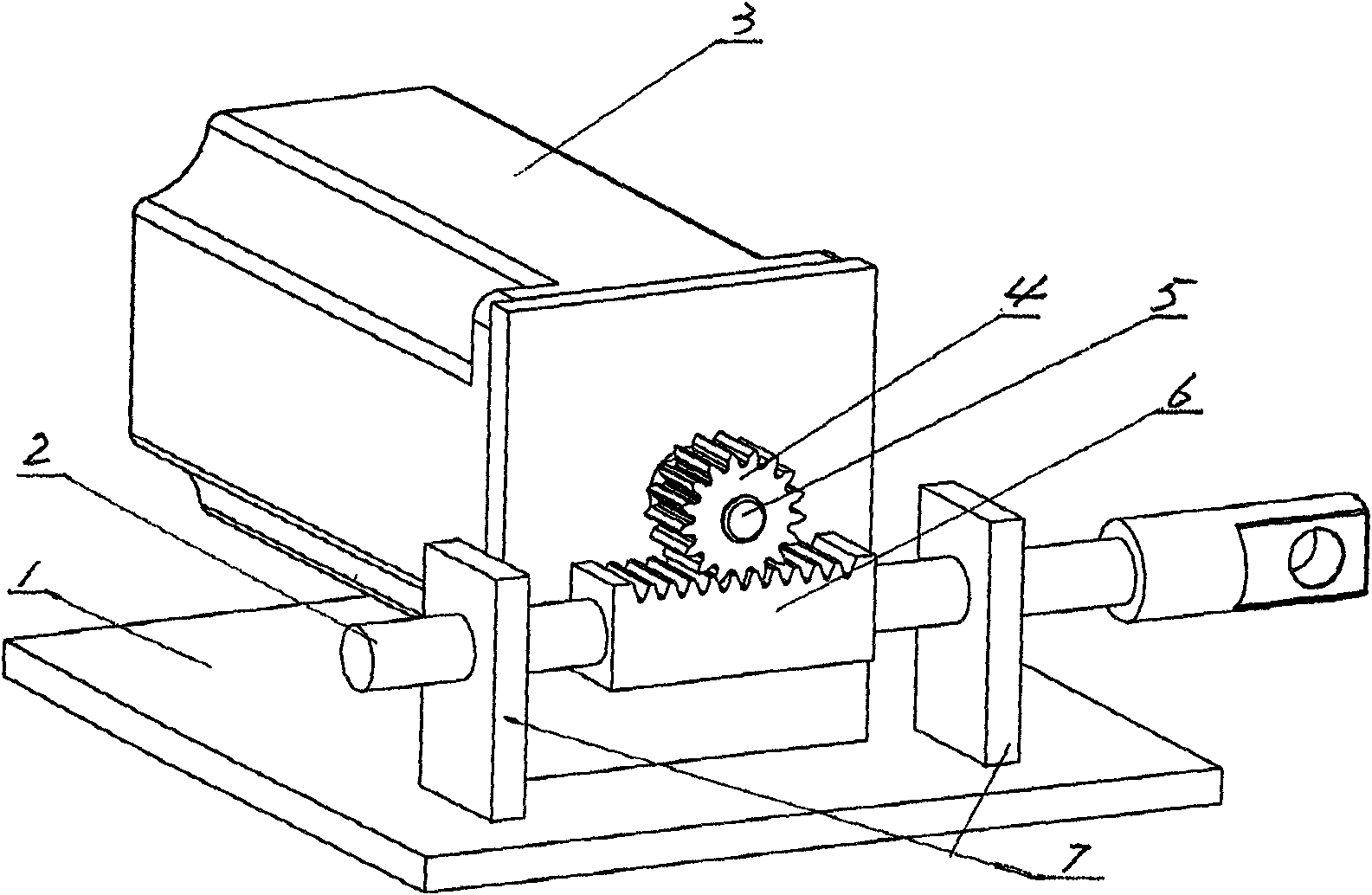
[0012] Such as figure 1 As shown, the electronically controlled driving device for the hydraulic spool of the present invention includes a base 1, which is flat and can be the shell of a machine or a vehicle in use, or the table top of an experimental platform. The base 1 is provided with a guide rod 2 and two support seats 7 . Both supporting bases 7 are flat plates, they are vertically arranged facing each other, and their lower sides are fixed on the base 1 . Concentric holes are processed on the two support bases 7, and both ends of the guide rod 2 slide through the concentric holes on the two support bases 7 and then protrude outside. connected. A motor 3 is arranged on the base 1 on one side of the guide rod 2, the motor is fixed on the base 1, a gear 4 is fixed on the output shaft 5 of the motor 3, and a rack 6 is fixed on the guide rod 2, and the gear and the rack Mesh together. When working, the gear 4 on the output shaft 5 is driven by the motor 3 to rotate, and ...


PUM


Abstract

The invention discloses an electrical control drive device for a hydraulic valve core, in particular an electrical control drive device for driving a valve core of a hydraulic valve. The electrical control drive device comprises a base and is characterized in that the base is provided with a guide rod and two support seats; the two support seats are both provided with concentric holes; two ends of the guide rod are of a sliding shape, pass through the concentric holes of the two support seats and extend out of the support seats; and one end of the guide rod is connected with a valve core of the hydraulic valve in an installation state. One side of the guide rod is provided with a motor; an output shaft of the motor and the guide rod are provided with gears and racks respectively; and the gears and the racks are meshed together. The electrical control drive device has simple production process and low production cost.

Description

technical field [0001] The invention relates to a power mechanism. Specifically, it is an electronically controlled drive device used to drive the hydraulic valve spool. Background technique [0002] It is known in the hydraulic valve manufacturing industry that the electronically controlled driving device used to drive the hydraulic valve spool is mainly an electromagnet driving device. This electromagnet driving device is widely used as a hydraulic valve control element for machinery, vehicles and various experimental platforms due to its compact structure and seamless connection with the electronic control system. But because the electromagnet of the electromagnet driving device is made up of parts such as coil, iron core and spring, and solenoid valve is made up of electromagnet and hydraulic valve again, make the external dimension of electromagnet can not be too big. And the size of the electromagnet is small, and its driving force is just small. Therefore, the driv...

Claims


Application Information

Patent Timeline
IPC IPC(8): F16K31/04F16K31/54
Inventor 张德恩张欲保汤久望邵立福陆凤翔邹少军陈新军
Owner 中国人民解放军63983部队
Why Eureka
Try Eureka