Method for detecting compressive strength of concrete by body sampling

A compressive strength, concrete technology, applied in the direction of strength characteristics, measuring devices, material inspection products, etc., can solve the problems of limited use, low precision, detection error and high detection cost, so as to ensure accuracy and realize representative sexual effect

Inactive Publication Date: 2010-01-06
张国志
View PDF0 Cites 13 Cited by
  • Summary
  • Abstract
  • Description
  • Claims
  • Application Information

AI Technical Summary

Problems solved by technology

However, there are still limitations in use and low precision
[0004] To improve the compressive strength test and evaluation of the deviation caused by the actual compressive strength of cast-in-place concrete components of the widely used reserved concrete standard curing test block and the same condition curing test block, once the reserved concrete sta...

Method used


Image

  • Method for detecting compressive strength of concrete by body sampling
  • Method for detecting compressive strength of concrete by body sampling

Examples


Embodiment 1

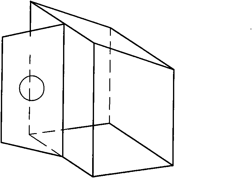
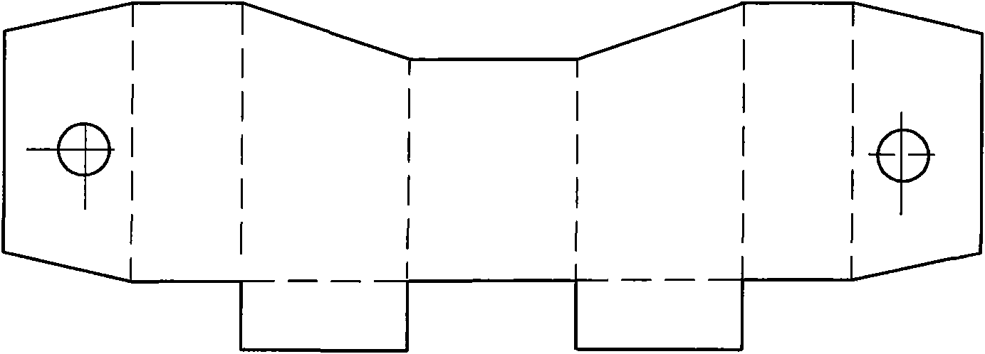
[0019] Q235 steel plate is used, the thickness is 2.0mm, the net size of the mold box is set as length × width × height = l × b × h = 100mm × 100 × 120mm, pressed into the attached figure 1 The mold box shown is used for pre-embedding in cast-in-place concrete components. When assembling the formwork of cast-in-place components, the mold box is suspended and fixed on the inside of the formwork. When pouring component concrete, a concrete compression test is formed in the mold box pieces. When the same conditions as the cast-in-place concrete components are maintained and reach the age, take out the mold box, and then take out the concrete specimen in the mold box, according to length × width × height = l × b × h = 100mm × 100 × 100mm, cut After grinding, the compressive data is obtained on a pressure testing machine.

Embodiment 2

[0021] Q235 steel plate is used, the thickness is 1.5mm, the net size inside the mold box is set as length × width × height = l × b × h = 80mm × 80 × 100mm, pressed into attached figure 1 The mold box shown is used for pre-embedding in cast-in-place concrete components. When assembling the formwork of cast-in-place components, the mold box is suspended and fixed on the inside of the formwork. When pouring component concrete, a concrete compression test is formed in the mold box pieces. When the same conditions as the cast-in-place concrete components are maintained and reach the age, take out the mold box, and then take out the concrete specimen in the mold box, according to length × width × height = l × b × h = 80mm × 80 × 80mm, cut After grinding, the compressive strength of the specimen is obtained on the pressure testing machine, which is used to detect and evaluate the compressive strength of the cast-in-place concrete body.


PUM


Abstract

The invention discloses a method for detecting compressive strength of concrete by body sampling. Once a method for detecting and assessing the practical compressive strength of a cast-in-place concrete member by using the compressive strengths of a reserved concrete standard curing test block and a curing test block under the same condition loses effectiveness, the prior detection method must adopt a rebound-ultrasonic or core drilling method to detect, but the detection error and detection expense of the two methods are large. The method comprises the following steps: pressing a die box which is embedded in the cast-in-place concrete member; when a template of the cast-in-place member is assembled, suspending and fixing the die box at the inside of the template; when concrete for the member is poured, forming a concrete compressive test piece in the die box; and when the concrete compressive test piece is cured to an age as the cast-in-place concrete member under the same condition, taking the die box out, then taking the concrete test piece in the die box out, cutting and smoothening the concrete test piece according to the prescribed size, and obtaining the compressive strength of the test piece on a pressure tester to be used for detecting and assessing the compressive strength of the cast-in-place concrete body. The method is applied to detecting and assessing the compressive strength of the concrete in the civil engineering.

Description

Technical field: [0001] The invention relates to a method for detecting concrete compressive strength by body sampling. Background technique: [0002] With the strengthening of our country's economic strength and the continuous improvement of the technical level, various construction projects are increasing. Concrete structure is one of the most widely used structural forms in domestic and foreign engineering construction. The quality of concrete construction directly affects the safety of concrete structure engineering and even the entire construction project. Therefore, how to effectively supervise and ensure the quality of concrete structure engineering is of great significance to improve the overall level of engineering construction quality in our country. The construction strength of concrete is directly related to the structural safety of the building. Whether the actual construction strength of the concrete poured on site meets the design strength requirements requir...

Claims


Application Information

Patent Timeline
IPC IPC(8): G01N3/00G01N33/38
Inventor 张国志
Owner 张国志
Why Eureka
Try Eureka