Method and device for allocating uplink control signal resource in multi-base station network

A technology for controlling signals and distributing devices, applied in the directions of space transmit diversity, diversity/multi-antenna systems, etc., can solve the problem of difficulty in ensuring the orthogonality of uplink detection signal patterns, and achieve the effects of avoiding conflicts, suppressing interference, and improving throughput

Active Publication Date: 2010-01-06
ALCATEL LUCENT SHANGHAI BELL CO LTD
View PDF0 Cites 10 Cited by
  • Summary
  • Abstract
  • Description
  • Claims
  • Application Information

AI Technical Summary

Problems solved by technology

However, since only one of the mobile terminals receiving the common service of multiple base stations allocates its uplink sounding signal pattern, if each base station independently alloc

Method used


Image

  • Method and device for allocating uplink control signal resource in multi-base station network
  • Method and device for allocating uplink control signal resource in multi-base station network
  • Method and device for allocating uplink control signal resource in multi-base station network

Examples


Embodiment Construction

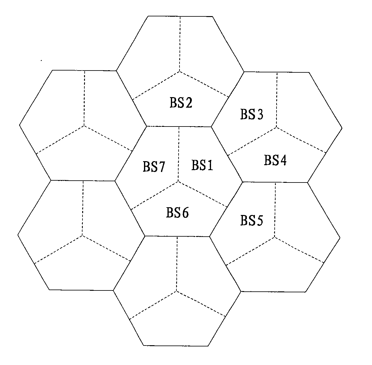
[0066] image 3 This is a schematic diagram of sector planning according to a specific embodiment of the present invention. Such as image 3 As shown, each cell is divided into three sectors, and each sector has a base station. Because of the relationship between the antenna signal direction of the base station and the distance, the mobile terminal in a sector is most likely to receive interference signals from its neighbors. The base station of the sector. For example, if a mobile terminal in the sector where the base station BS1 is located receives the service of the base station BS1, the most likely interference signal it receives comes from the base stations BS2, BS3, BS4, and BS5. The base station most likely to serve a mobile terminal in cooperation should also be a neighboring base station. For example, base station BS1 and base station BS5 can cooperatively serve one mobile terminal, and base stations BS1, BS2, and BS3 can also cooperatively serve one mobile terminal.

...


PUM


Abstract

The invention provides a method and a device used for allocating uplink control signal patterns for a mobile terminal in a multi-base station cooperative MIMO network. The method comprises the following steps: a, obtaining service relationship information of one or more mobile terminals needing to use the same time frequency resource to serve; b, determining whether the base station has a right to allocate the uplink control signal patterns to one or more mobile terminals according to the service relationship information; and c, allocating different uplink control signal patterns to each mobile terminal in one or more mobile terminals to which the base station has the right to allocate the uplink control signal patterns. The technical scheme provided by the invention has the advantages of supporting the joint allocation of the uplink control signal patterns between the cooperated base stations and using allocated uplink control signal patterns to allocate. Therefore, little interactive information is transmitted between the cooperated base stations only through a Backbone network. The uplink control signal patterns do not need to be allocated in a centralized mode by a dispatching device or other devices.

Description

Technical field [0001] The present invention relates to the allocation of uplink control signal resources in a wireless communication network, and in particular to a method and device for allocating uplink control signal patterns through multi-base station cooperation in a wireless communication network based on multiple input multiple output (MIMO). Background technique [0002] In order to increase the system user capacity, the existing wireless communication network often uses a low frequency reuse factor, that is, all cells share the same time-frequency resources, and the inter-cell interference caused by the low frequency reuse factor restricts the downlink capacity An important factor of For a mobile terminal located at the edge of a cell (that is, the area between adjacent cells), while receiving useful signals from the base station to which it belongs, it will also receive signals from other base stations using the same time-frequency resources. The signals of the other ...

Claims


Application Information

Patent Timeline
IPC IPC(8): H04B7/02H04B7/04
Inventor 吴克颖李栋朱孝龙
Owner ALCATEL LUCENT SHANGHAI BELL CO LTD
Why Eureka
Try Eureka