Backlight module and optical plate thereof

A backlight module and optical board technology, applied in optics, optical components, nonlinear optics, etc., can solve the problems of reducing light utilization, increasing light transmission interface loss, light loss, etc.

Inactive Publication Date: 2010-01-13
HONG FU JIN PRECISION IND (SHENZHEN) CO LTD +1
View PDF0 Cites 10 Cited by
  • Summary
  • Abstract
  • Description
  • Claims
  • Application Information

AI Technical Summary

Problems solved by technology

[0005] However, when the light is transmitted in the prism sheet 10 and the upper diffusion sheet 14, part of the light will be absorbed and cause light loss; The number of interfaces increases the interface loss of light transmission and reduces light utilization

Method used


Image

  • Backlight module and optical plate thereof
  • Backlight module and optical plate thereof
  • Backlight module and optical plate thereof

Examples


Embodiment Construction

[0020] The backlight module and its optical board of the present invention will be further described in detail below with reference to the drawings and embodiments.

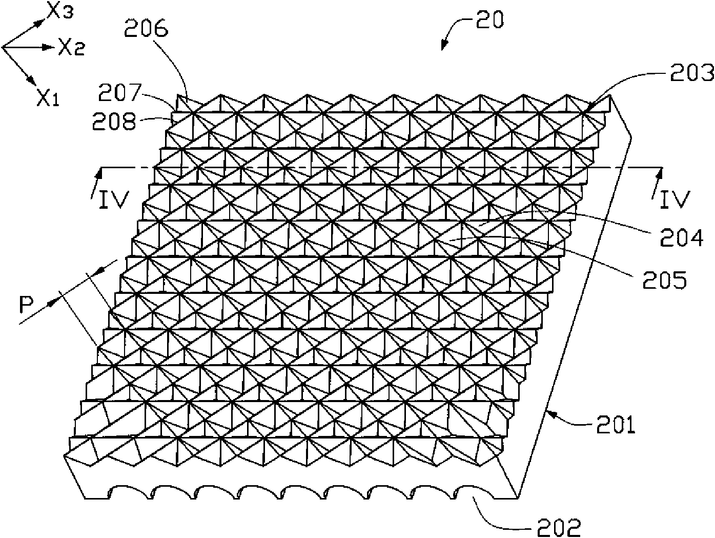
[0021] See image 3 and Figure 4 , shows the optical plate 20 according to the preferred embodiment 1 of the present invention, which is composed of a transparent body, and the transparent body includes a first surface 201 and a second surface 203 opposite to the first surface 201 . The first surface 201 has a plurality of elongated arc-shaped grooves 202, the second surface 203 has a plurality of triangular pyramid-shaped grooves 204 and a plurality of quadrangular pyramid-shaped grooves 205, and each quadrangular pyramid-shaped groove 205 is composed of Surrounded by four triangular pyramid-shaped grooves 204 .

[0022] Specifically, in this embodiment, the vertical section of each elongated arc-shaped groove 202 on the first surface 201 is semi-circular arc-shaped. The radius of the arc in the elongated ar...


PUM

PropertyMeasurementUnit
angleaaaaaaaaaa
thicknessaaaaaaaaaa

Abstract

An optical plate comprises a transparent body which comprises a first surface and a second surface opposite to the first surface; wherein, the first surface is provided with a plurality of long strip arc grooves; the second surface is provided with a plurality of triangular pyramid shaped grooves and rectangular pyramid shaped grooves; each rectangular pyramid shaped groove is enclosed by four triangular pyramid shaped grooves. The invention also provides a backlight module adopting the optical plate. The backlight module has the advantages of improving effective utilization ratio of light and enjoying uniformity of light emission.

Description

technical field [0001] The invention relates to a backlight module and its optical board, in particular to a backlight module for liquid crystal display and its optical board. Background technique [0002] See figure 1 , shows a conventional direct-lit backlight module 100, which includes a frame 11, a plurality of light sources 12 disposed inside the frame 11, and a diffusion plate 13 disposed above the light sources 12 and covering the frame 11. [0003] In use, the light generated by the plurality of light sources 12 enters the diffusion plate 13 and is diffused. However, after being diffused by the diffuser plate 13, the angles at which light emerges from the diffuser plate 13 become more chaotic, so that its brightness in a specific viewing angle range is not high; It is still often difficult for the plate 13 to directly diffuse the light from the light source 12 evenly, so that the light emitted from the diffuser plate 13 is prone to light source afterimages, that is...

Claims


Application Information

Patent Timeline
Patent Type & Authority Applications(China)
IPC IPC(8): G02F1/13357G02B6/00
Inventor 章绍汉
Owner HONG FU JIN PRECISION IND (SHENZHEN) CO LTD
Why Eureka
Try Eureka