

Sealed cell
A technology for sealing batteries and sealing bodies, which is applied in the directions of batteries, secondary batteries, battery pack components, etc., can solve the problems of floating of the sealing body 104, insufficient welding, poor welding, etc., so as to suppress floating, prevent poor welding and floating or the effect of tilt suppression
Inactive Publication Date: 2010-01-13
HITACHI MAXELL ENERGY LTD
View PDF4 Cites 10 Cited by
- Summary
- Abstract
- Description
- Claims
- Application Information
AI Technical Summary
Problems solved by technology
In this case, floating and inclination of the sealing body 104 occurs, and if welding is performed in this state, the welding becomes insufficient, resulting in poor welding.
Method used
View moreImage
Smart ImageViewing Examples

Examples
Embodiment 1
[0078] Example 1 in Figure 6 In (a), the taper angle α is α=17°, the plate thickness t of the sealing body 2 is t=0.8 mm, and the taper depth d is d=0.5 mm. If expressed by the ratio of the depth d to the plate thickness t, it is 62.5%.
Embodiment 2
[0079] Example 2 in Figure 8 In (a), the taper angle α is α=45°, the plate thickness t of the sealing body 2 is t=0.8 mm, and the taper depth d is d=0.15 mm. It is 18.8% when represented by the ratio of the depth d to the plate thickness t.
Login to View More PUM
| Property | Measurement | Unit |
|---|---|---|
| thickness | aaaaa | aaaaa |
Abstract
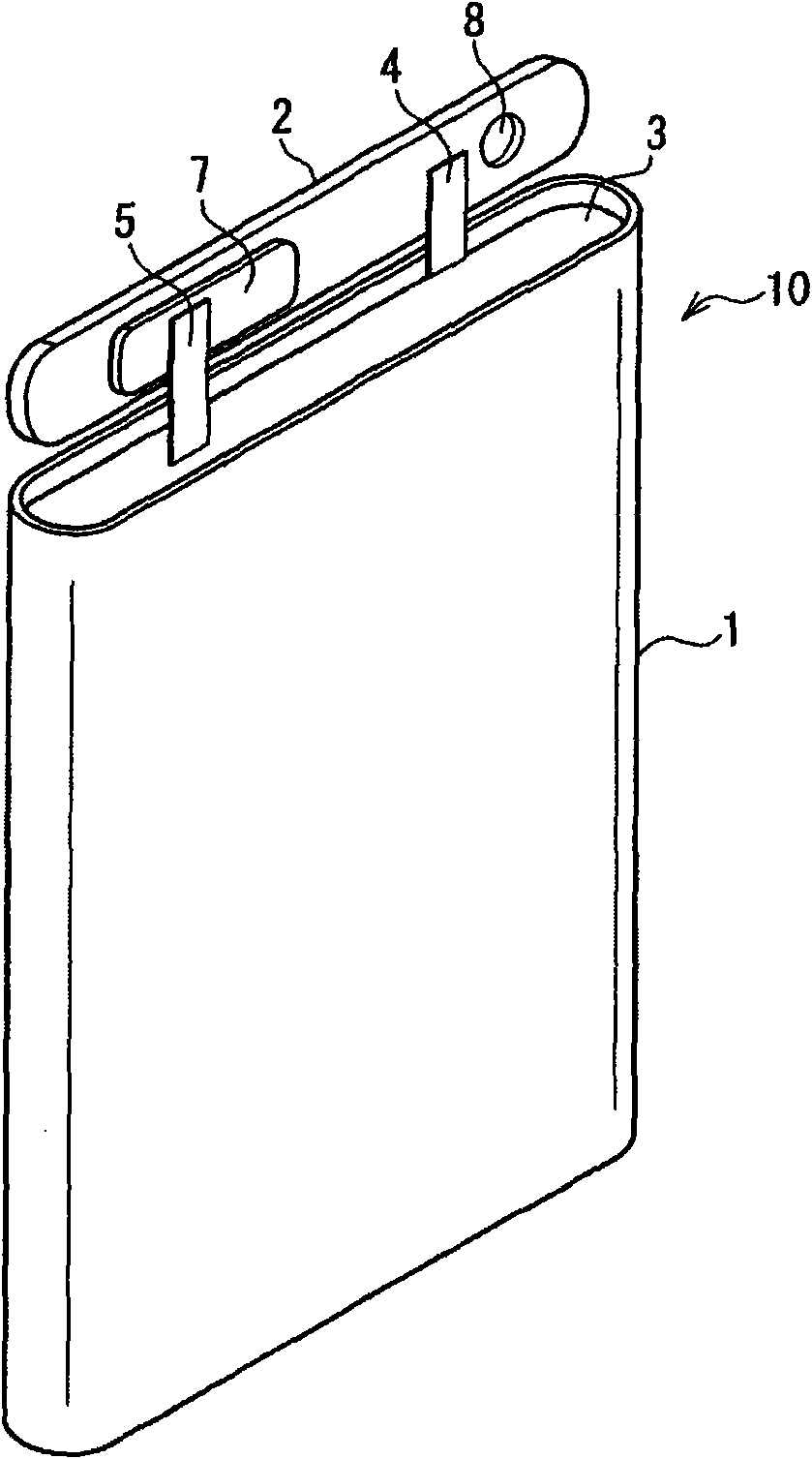
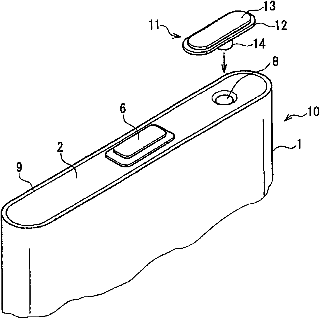
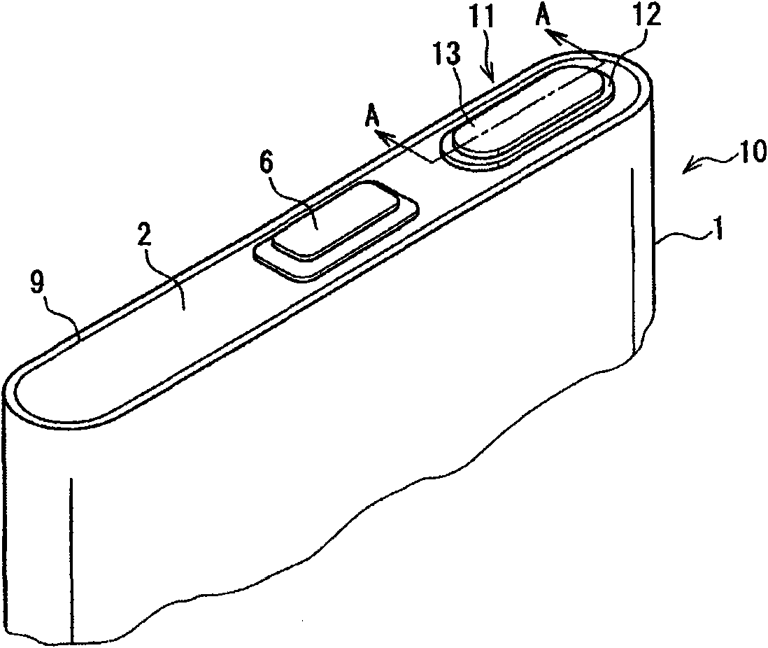
The present invention provides a sealed cell which can restrain floating and inclining of a sealing body, and avoid bad welding. The sealed cell adopts an opening of a sealing body (2) for sealing, wherein, the opening is used for canning externally, a sealing body (11) is inserted into a hole (8) formed on the sealing body (2), the hole (8) forming makes the diameter increased following a surface of a taper face (15) towards to the package body (2), an interval (16) forms between the taper face (15) and the sealing body (11), and the sealing body (11) is welded on the package body (2). The taper face (15) is benefit for eccentricity and inclining of the sealing body (11) in installing. A biting sheet generated in inserting the sealing body is stored in the interval (16). The floating and inclining of the sealing body (11) caused by sandwiching of the biting sheet can be restrained and bad welding is avoided.
Description
technical field [0001] The present invention relates to a sealed battery, and more particularly to a sealed battery including a sealing body that seals a liquid injection hole for an electrolytic solution. Background technique [0002] In recent years, small and lightweight electronic devices such as mobile phones and mobile devices have become popular. As batteries used for these electronic devices, prismatic sealed batteries are known. Figure 11 A perspective view showing an example of a conventional sealed battery. In the sealed battery 100 , the opening of a bottomed cylindrical outer can 101 containing an electrode body (not shown) is sealed with a sealing body 102 . A negative electrode terminal 103 and a sealing body 104 are attached to the sealing body 102 . The sealing body 104 seals the electrolyte injection hole. [0003] Figure 12 yes Figure 11 Sectional view of the BB line. The sealing body 104 is formed by pressure-welding an aluminum plate 105 formed o...
Claims
Login to View More Application Information
Patent Timeline
 Patent Type & AuthorityApplications(China)
IPC IPC(8): H01M10/00H01M2/08H01M2/36
CPCY02E60/12Y02E60/10H01M2220/30
Inventor浦野和昭中西健二
OwnerHITACHI MAXELL ENERGY LTD