Clamping and positing device capable of automatically aligning center and using method thereof

A clamping positioning and automatic technology, applied in workpiece clamping devices, manufacturing tools, etc., can solve problems such as the inability to guarantee the constant reference position of the center of the part, the inability to solve quality problems, and the troubled production of enterprises. It is easy to process, assemble, eliminate Position offset, the effect of improving efficiency

Inactive Publication Date: 2010-01-20
李梓鸿 +1
View PDF0 Cites 58 Cited by
  • Summary
  • Abstract
  • Description
  • Claims
  • Application Information

AI Technical Summary

Problems solved by technology

Now the common clamping positioning is based on one side (surface) or two adjacent sides (surfaces) of the part, so that for the processed part, the center is the reference part, if the error of the external dimension change is enough to affect the product When the quality is high, this clamping and positioning method cannot solve the quality problem
That is, the center reference position of the part cannot be guaranteed to remain unchanged
Lead to a large number of substandard products, and sometimes even seriously trouble the production of enterprises
[0003] Many enterprises have been plagued by the above quality problems for a long time, especially the silk screen printing process requires printing on the surface of plastic parts or glass parts, which used to be positioned on two adjacent sides (surfaces), when the printed graphics required to be based on the center of the part A large number of substandard products will be produced, which not only delays the production plan but also causes huge waste to the enterprise.

Method used


Image

  • Clamping and positing device capable of automatically aligning center and using method thereof
  • Clamping and positing device capable of automatically aligning center and using method thereof
  • Clamping and positing device capable of automatically aligning center and using method thereof

Examples


Embodiment Construction

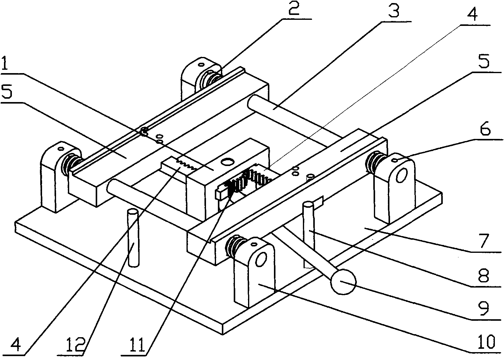
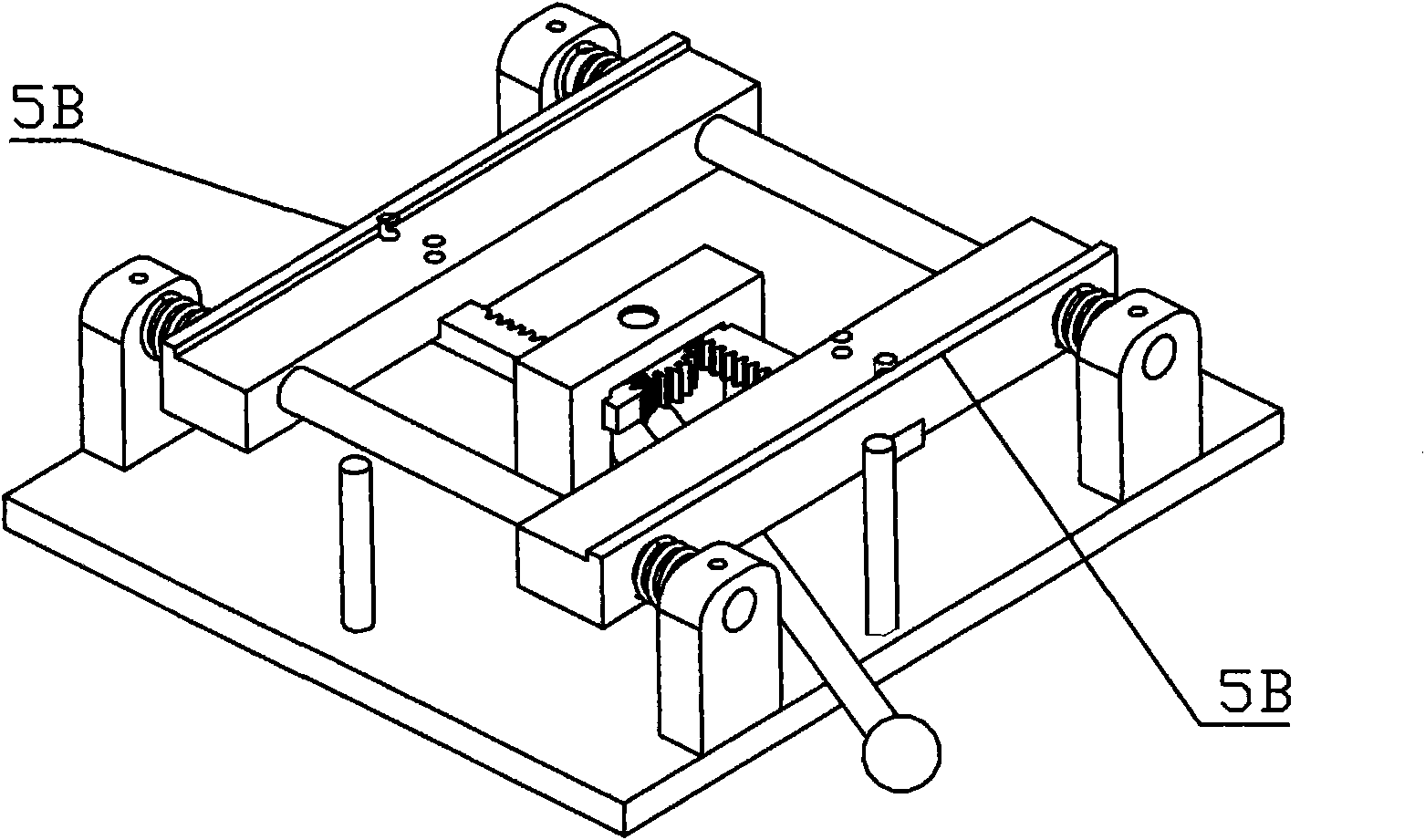
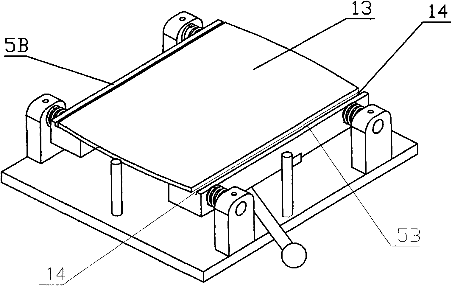
[0033] 1. The clamping and positioning device that can automatically align the center is characterized in that it includes a driving mechanism, a clamping mechanism, a guiding mechanism and a supporting mechanism. The driving mechanism includes a driving device and a driving force transmission device. The clamping mechanism includes a positioning plate 5, a guide The mechanism includes a guide column 3, the supporting mechanism includes a base 7, a fixed seat 10, the driving mechanism, the clamping mechanism and the guiding mechanism are supported by the supporting mechanism, the driving mechanism drives the positioning plate 5, and the guiding mechanism makes the positioning plate 5 move according to the guided moving route. Move, thereby, the positioning plate 5 can clamp the workpiece 13 to be processed, and make the center reference position of the workpiece 13 to be automatically located at the station positioned to the center (center line or center point).

[0034] 2. As ...


PUM


Abstract

The invention provides a clamping and positing device capable of automatically aligning center and a using method thereof, relating to a tooling clamp capable of automatically aligning center and being used in a plurality of fields of mechanical manufacture, printing, surface coating, electronic assembly and the like. The device comprises a driving mechanism, a clamping mechanism, a guiding mechanism and a supporting mechanism, wherein, the driving mechanism comprises a driving device and a driving force transmission device; the clamping mechanism comprises a positioning board (5); the supporting mechanism comprises a base (7) and a fixed seat (10); the driving mechanism, the clamping mechanism and the guiding mechanism are supported by the supporting mechanism; the driving mechanism drives the positioning board (5); the guiding mechanism ensures that the positioning board (5) moves according to a guided movement route; thus, the positioning board (5) can clamp a piece (13) to be processed, and the central reference position of the piece (13) to be processed is automatically positioned on the station for positioning a centre (central line or central point). The device can automatically align center and eliminate central line / point position offset.

Description

technical field [0001] The invention relates to a mechanical device, in particular to a tooling fixture capable of automatic centering. The invention also relates to methods of use of the device. Background technique [0002] In the field of production and processing, the processing of many parts is required to be carried out at the position of the part determined by the design. During processing, it needs to be clamped and positioned, and then processed. Nowadays, the common clamping positioning is based on one side (face) or two adjacent sides (faces) of the part, so that for the processed part, the center is the reference part. If the error of the external dimension change is enough to affect the product When the quality is high, this clamping and positioning method cannot solve the quality problem. That is, the center reference position of the part cannot be guaranteed to remain unchanged. Lead to a large number of substandard products, and sometimes even seriously tr...

Claims


Application Information

Patent Timeline
Patent Type & Authority Applications(China)
IPC IPC(8): B25B11/00
Inventor 李梓鸿聂建国
Owner 李梓鸿
Why Eureka
Try Eureka