Card edge connector

A technology for card edge connectors and connecting parts, which is applied in the direction of connection, two-part connection device, and parts of the connection device, so as to improve the connection stability and reliability of use, and improve the yield and service life.

Active Publication Date: 2010-01-20
深圳市乾德电子股份有限公司
View PDF0 Cites 2 Cited by
  • Summary
  • Abstract
  • Description
  • Claims
  • Application Information

AI Technical Summary

Problems solved by technology

[0004] The purpose of the embodiment of the present invention is to provide a card edge connector, aiming to solve the technical problem in the prior art that the welding points of the bottom edges of the two auxiliary support frames and the welding feet of the connecting terminals are in the same plane, and at the same time ensure that the connecting terminals The connection point between the welding pin and the circuit board is not affected by the insertion and relay of the electronic card, so as to improve the connection stability and reliability of the connector

Method used


Image

  • Card edge connector
  • Card edge connector
  • Card edge connector

Examples


Embodiment Construction

[0028] In order to make the object, technical solution and advantages of the present invention clearer, the present invention will be further described in detail below in conjunction with the accompanying drawings and embodiments. It should be understood that the specific embodiments described here are only used to explain the present invention, not to limit the present invention.

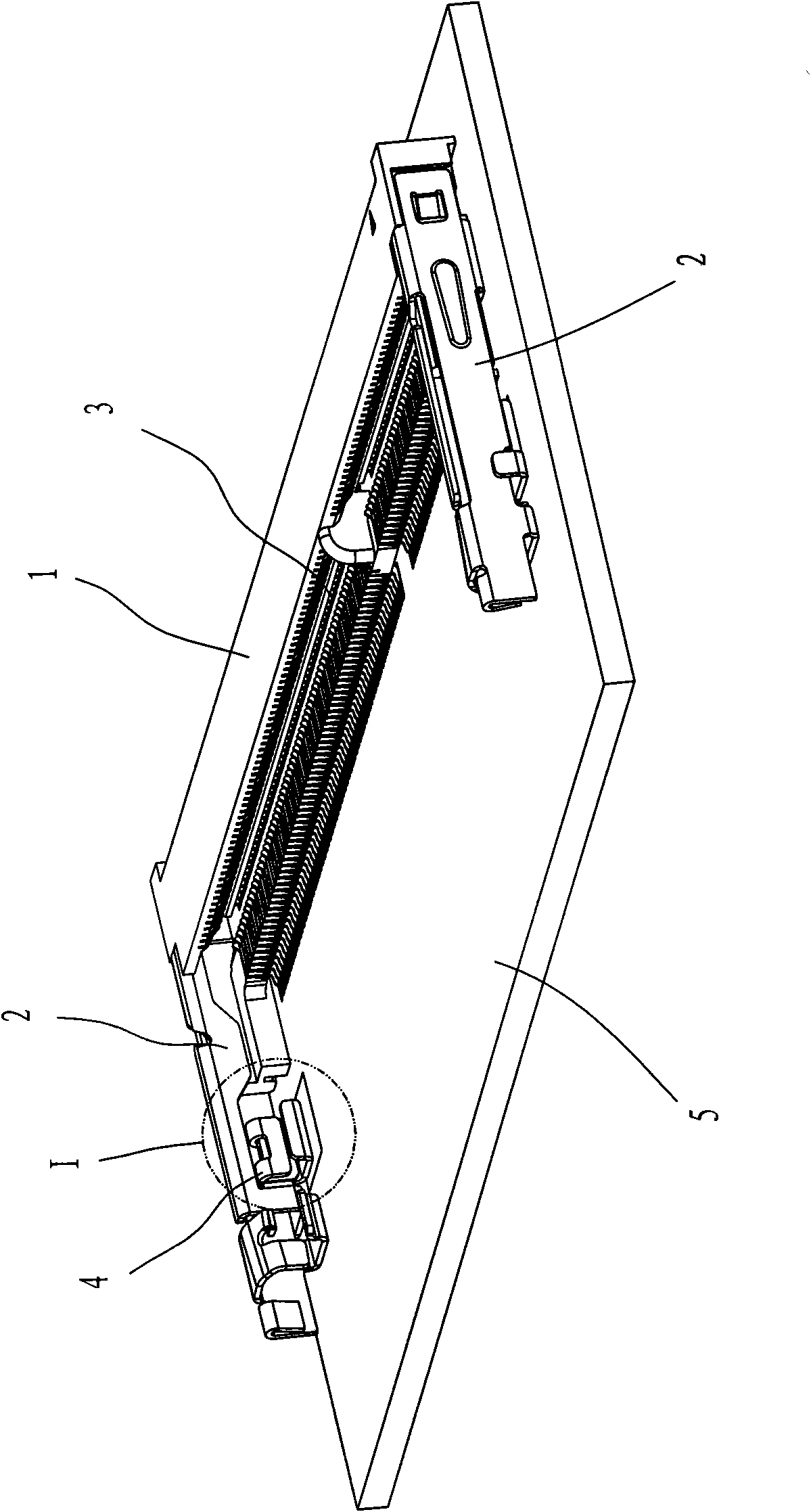
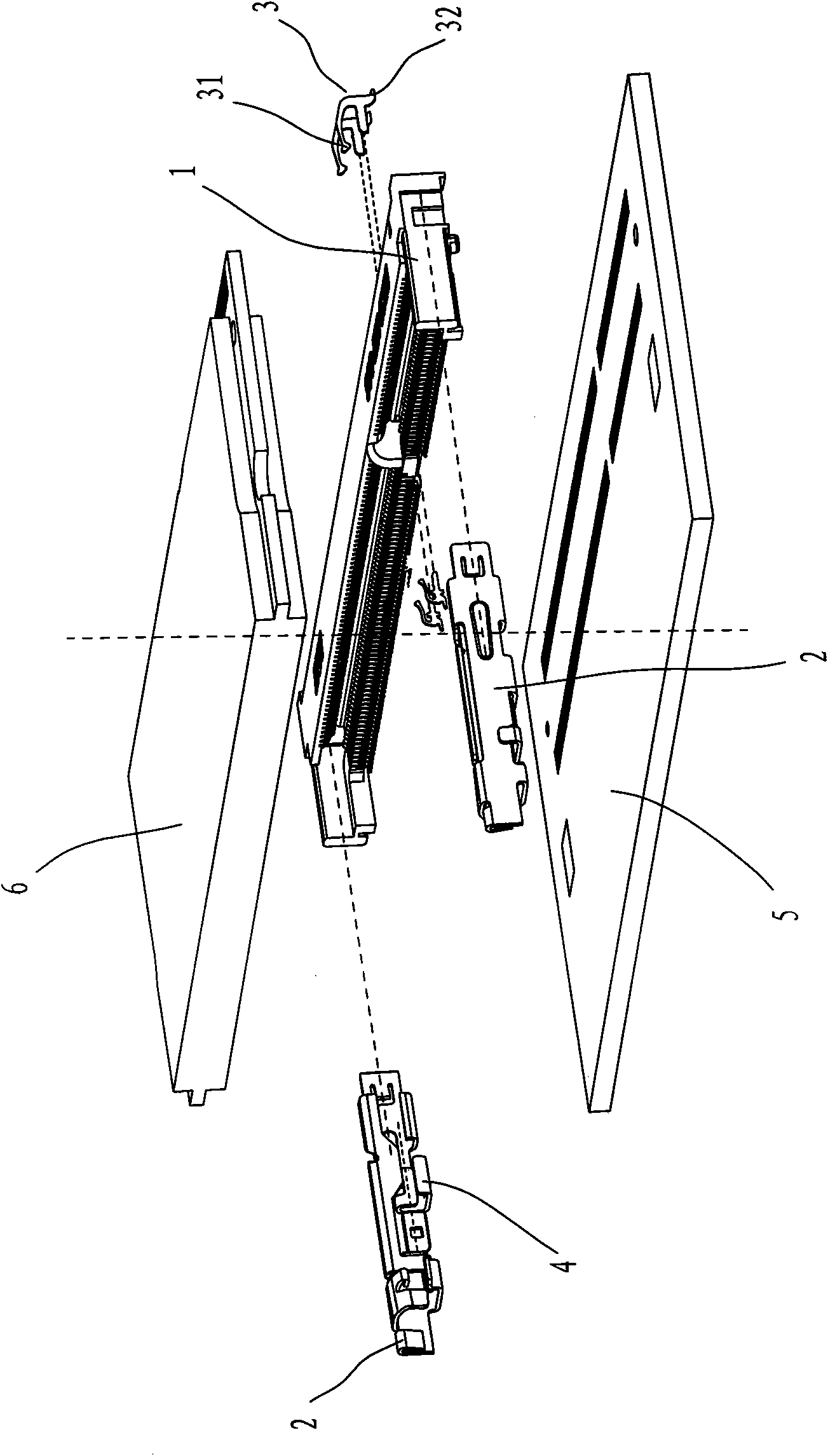
[0029] Such as figure 1 , figure 2 As shown, the embodiment of the present invention mainly includes: a strip-shaped insulating body seat 1 containing a plurality of sockets, a group of connecting terminals 3 arranged in parallel, and two cantilever support frames 2 arranged at both ends of the insulating body seat 1 The upper end of each connecting terminal 3 has a contact portion 31, which can be positioned in the corresponding socket provided on the insulating body seat 1, and the welding pin 32 provided at the lower end extends outside the insulating body seat 1 and connects with the circuit ...


PUM


Abstract

The invention provides a card edge connector, which comprises a strip insulating body seat provided with a plurality of jacks, a group of connecting terminals arranged in parallel and two cantilever supporting frames arranged at the two ends of the insulating body seat, wherein the connecting terminals are inserted into the jacks of the insulating body seat to form a group of spliced electrodes electrically connected with a circuit board; and each of the cantilever supporting frames is provided with an auxiliary supporting frame which can be connected with the circuit board, and the auxiliary supporting frame is sleeved and hinged with the corresponding cantilever supporting frame mutually. Through the micro-clearance fit between the auxiliary supporting frames and the cantilever supporting frames, the card edge connector can solve the technical problem that hemlines of the auxiliary supporting frames and welded pins of the connecting terminals are in the same plane, effectively ensures that the welded pins on the connecting terminals and circuit board connecting points are not swayed under the influence of an external force for inserting and extracting an electronic card, improves the connecting stability and the use reliability of the connector, and correspondingly improves the yield and the service life of the connector.

Description

technical field [0001] The invention relates to a connector structure in electronic products, in particular to a card edge connector used for fixing flat or strip-shaped electronic cards. Background technique [0002] With the development of electronic technology, various flat or strip electronic cards have been widely used in various electronic equipment (such as electronic communication equipment, computers, etc.). The connection terminals of the circuit board are electrically connected to the circuit board through soldering feet, and the connector needs to fix the electronic card at the same time. At present, the existing connector mainly includes: a strip-shaped insulating body seat containing multiple jacks, a group of connecting terminals arranged in parallel, and two cantilever arms arranged at both ends of the insulating body seat for fixing the connector. Support frame; the upper end of each connecting terminal has a contact portion, which can be placed in the sock...

Claims


Application Information

Patent Timeline
Patent Type & Authority Applications(China)
IPC IPC(8): H01R12/18H01R13/629H01R13/639
CPCH01R12/721H01R12/707H01R12/88H01R23/7063H01R23/7068H01R23/684
Inventor 王涧鸣苏敬舜
Owner 深圳市乾德电子股份有限公司
Why Eureka
Try Eureka