Interlocking device of circuit breaker

A technology of interlocking device and circuit breaker, which is applied in the direction of circuits, electrical components, electric switches, etc., can solve the problems that cannot meet the safety maintenance requirements of circuit breakers, it is difficult to realize single lock, complicated structure, etc., and achieve simple structure and low cost , the effect of convenient operation

Pending Publication Date: 2020-06-30
SHANGHAI RENMIN ELECTRICAL APP WORKS
View PDF1 Cites 0 Cited by
  • Summary
  • Abstract
  • Description
  • Claims
  • Application Information

AI Technical Summary

Problems solved by technology

However, the structure of the existing circuit breaker interlocking mechanism is relatively complicated, and it is difficult to realize multiple combinations such as single lock and several interlocks, so it cannot meet the safety maintenance requirements of different users and different occasions for circuit breakers

Method used


Image

  • Interlocking device of circuit breaker
  • Interlocking device of circuit breaker
  • Interlocking device of circuit breaker

Examples


Embodiment 1

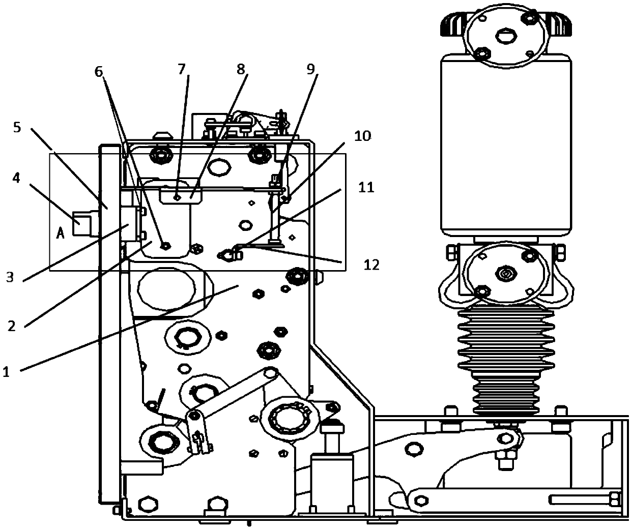
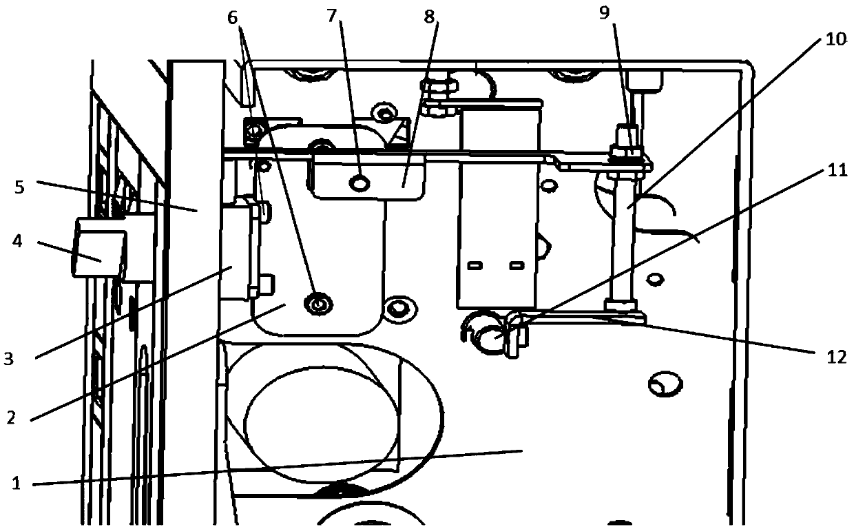
[0026] An interlocking device for a circuit breaker, such as figure 1 As shown, there is a fastener 6 on one side of the installation plate 2, which is fixedly installed on the side plate 1 of the circuit breaker. The key lock 3 is fixed and installed on the other side of the installation plate 2 with the fastener 6. The key lock 3 is inserted with a key. 4 and pass through the panel 5 to expose outside the circuit breaker. One end of the pin 7 passes through the connecting rod 8, and the other end is riveted with the mounting plate so that the connecting rod 8 can rotate freely around the axis of the pin 7. The other end of the connecting rod 8 is connected with a nut 9 Fix the screw 10, adjust the protruding length of the screw 10 through the adjusting nut 9, and fix an L-shaped first curved plate 12 on the tripping half shaft 11, and the enlarged assembly diagram is as follows figure 2 shown.

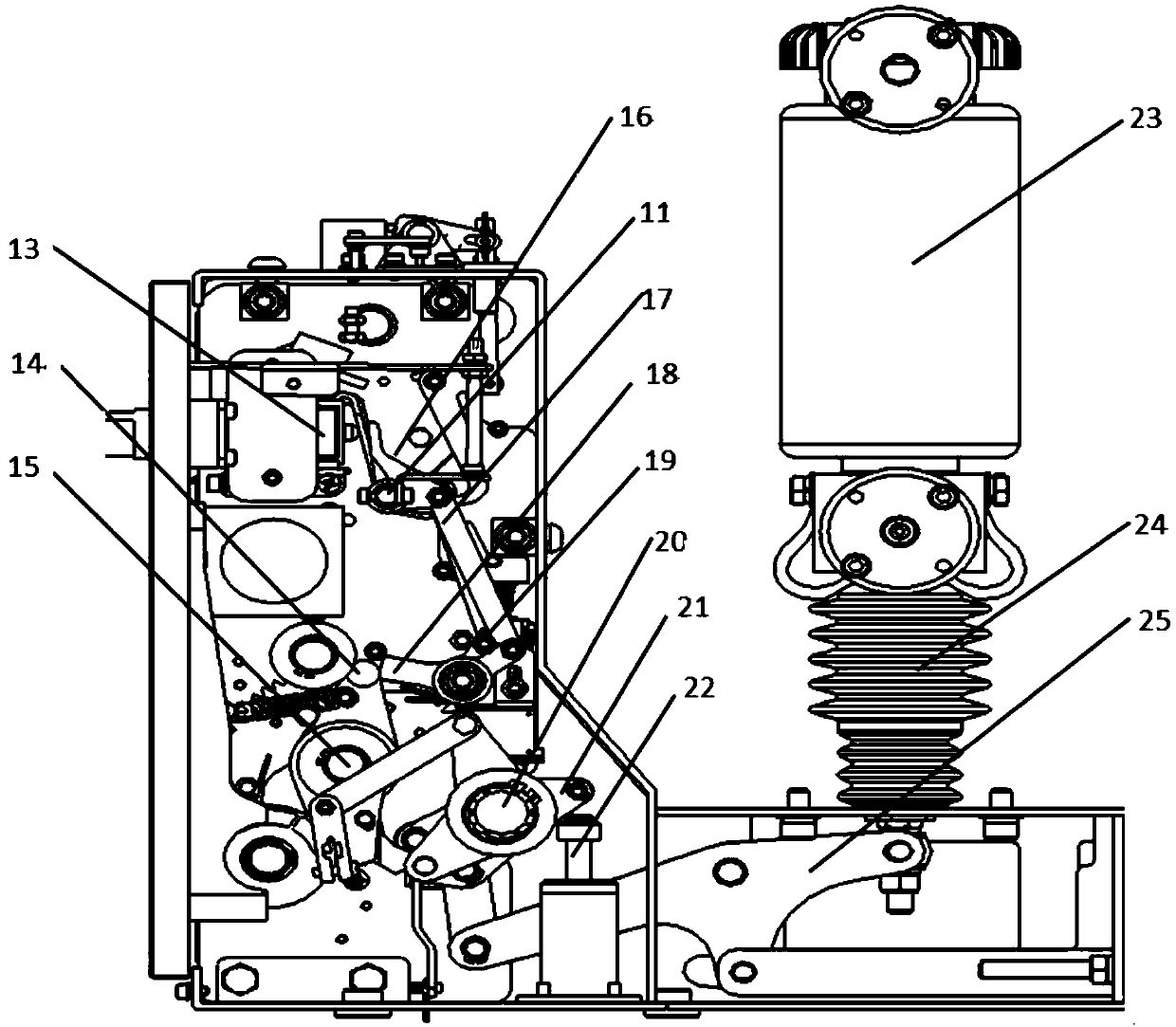
[0027] Such as image 3 As shown, the closing holding pawl 18 is tangent to t...


PUM


Abstract

The invention relates to an interlocking device of a circuit breaker. The interlocking device is used for starting a closing latch unit, so that an opening latch unit (15) is separated from the closing latch unit. A mounting plate (2) is fixedly mounted on a side plate (1) of a shell through a fastener (6). The interlocking device comprises a key lock (3), a connecting rod (8), a screw (11) and afirst bent plate (12); one end of the connecting rod (8) is arranged above an ejector rod of the key lock (3) and makes contact with the ejector rod of the key lock (3); the bottom of the other end ofthe connecting rod (8) is fixedly connected with the screw (11); and the first bent plate (12) is arranged at the bottom of the screw (11). The middle part of the connecting rod (8) is rotationally fixed on the mounting plate (2) through a pin (7), and one end of the first bent plate (12) is fixedly arranged on a tripping half shaft (11) and rotates together with the tripping half shaft (11). Compared with the prior art, the device is simple in structure, convenient to operate, low in cost, safe and reliable.

Description

technical field [0001] The invention relates to the technical field of circuit breakers, in particular to an interlock device of a vacuum circuit breaker. Background technique [0002] "Vacuum circuit breaker" is named because the arc extinguishing medium and the insulating medium of the contact gap after arc extinguishing are high vacuum; it has the advantages of small size, light weight, suitable for frequent operation, and no maintenance for arc extinguishing. It is widely used in power grid. Vacuum circuit breaker is an indoor power distribution device in 3-10kV, 50Hz three-phase AC system, which can be used for protection and control of electrical equipment in industrial and mining enterprises, power plants, and substations, especially suitable for oil-free, less In places where maintenance and frequent operations are used, circuit breakers can be configured in central cabinets, double-layer cabinets, and fixed cabinets to control and protect high-voltage electrical eq...

Claims


Application Information

Patent Timeline
IPC IPC(8): H01H71/10H01H9/20
CPCH01H9/20H01H71/10
Inventor 姚平辉江怿骏
Owner SHANGHAI RENMIN ELECTRICAL APP WORKS
Why Eureka
Try Eureka