A method and apparatus having improved handling of state transitions
A state and communication state technology, applied in the fields of computer programs, wireless communication networks, and computer program products, can solve the problems of impossible communication, consumption of wireless resources and battery resources, etc.
Active Publication Date: 2010-01-20
BLACKBERRY LTD
0 Cites 2 Cited by
AI-Extracted Technical Summary
Problems solved by technology
[0009] URA_PCH and CELL_PCH are paging states in which communication from UE t...
Method used
[0080] The serial port 930 in FIG. 8 may typically be implemented in a personal digital assistant (PDA) type mobile station for which synchronization with a user's desktop computer (not shown) may be desirable, But the serial port 930 is an optional device component. Such a port 930 may allow a user to set preferences through an external device or software applicatio...
Abstract
A method, in a wireless communications device, for transitioning between communication states, the wireless communications device compliant for use in a Universal Mobile Telecommunications System (UMTS), the method comprising: checking for radio bearer mapping information for the communication state being transitioned to prior to sending an update message, where the transition between communication states is not a transition from a paging state to a bidirectional communication state using shared channels; and transitioning to the state to be transitioned to using the checked radio bearer mapping information for that state and sending the update message.
Application Domain
Connection management
Technology Topic
TelecommunicationsMobile telecommunication systems +3
Image
Examples
- Experimental program(1)
Example Embodiment
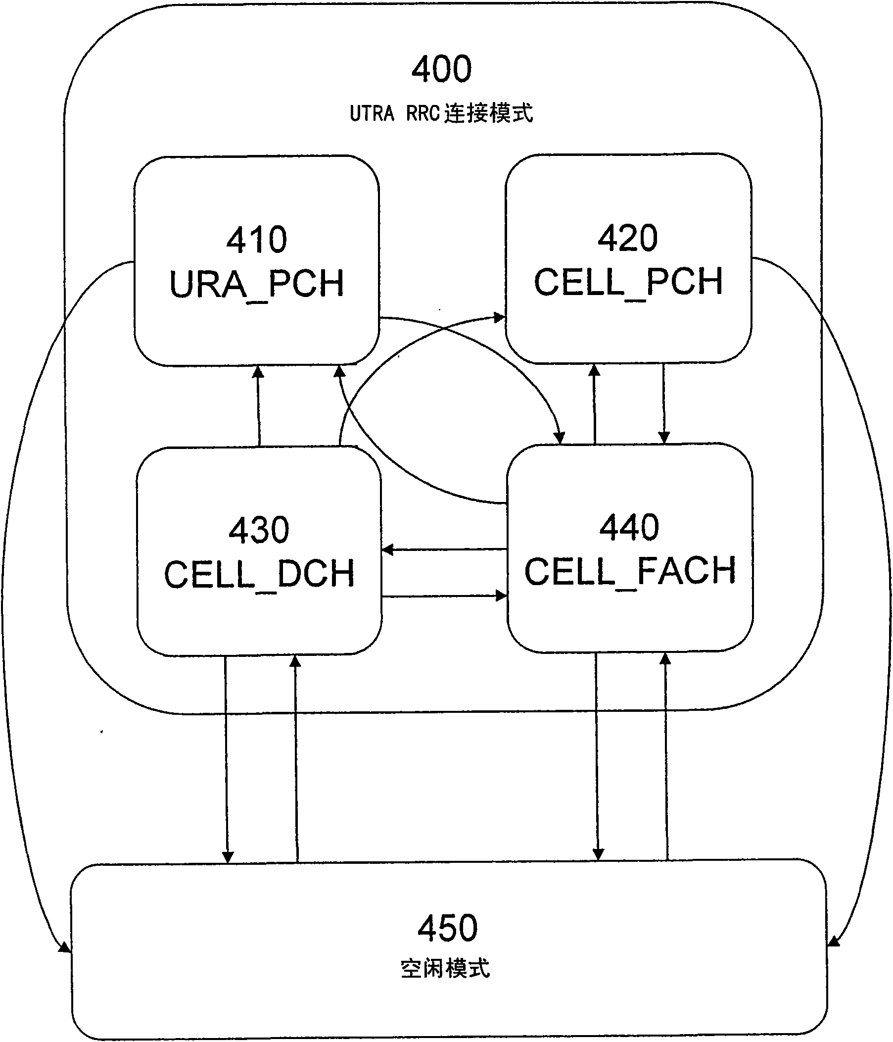
[0032] According to the scheme described here, it is recognized that when the third-generation wireless communication device moves from the paging state (such as URA_PCH or CELL_PCH) to CELL_FACH in order to perform the CELL or URA update process, it will usually try to check the radio bearers stored in SRB 1 to 4 Information, and move to the IDLE state when the check fails.
[0033] Correspondingly, the requirements for checking the radio bearer mapping information of SRB1-4 in CELL_PCH/URA_PCH have been changed, so that in this particular case, the UE does not need to perform any checks mentioned in section 8.5.21. While performing the CELL update process in the CELL_PCH or URA_PCH state or the URA update process in the URA_PCH state, the UE transitions to the CELL_FACH state, and then sends cell update/URA update (CELLUPDATE/URA UPDATE) on SRB0.
[0034] If SRB1 does not have FACH mapping, UTRAN will send a cell update confirmation/URA update confirmation (CELL UPDATE CONFIRM/URA UPDATE CONFIRM) message on SRB0. When receiving CELL UPDATE CONFIRM, if UTRAN has instructed the UE to move to CELL_DCH, the UE can directly configure DCH and move to CELL_DCH. Therefore, the UE does not need RACH/FACH mapping for SRB1-4.
[0035] When receiving URA UPDATE CONFIRM or CELL UPDATE CONFIRM, if UTRAN has instructed the UE to move to CELL_PCH or URA_PCH, the UE does not need RACH or FACH mapping and can directly jump to CELL_PCH or URA_PCH as indicated. This saves unnecessary checks on SRB1-4 mapping and configuration of RACH or FACH mapping, while still allowing exit from the CELL_PCH or URA_PCH state.
[0036] Correspondingly, when exiting CELL_PCH or URA_PCH, the radio bearer mapping check is reduced. For example, for the UE to perform a CELL or URA update process, in order to send a CELLUPDATE or URAUPDATE message, the UE will first transfer from CELL_PCH or URA_PCH to CELL_FACH. The UE is arranged to omit the radio bearer mapping check when moving to the CELL_FACH state. Therefore, even if an appropriate radio bearer is not established, the UE does not move to an idle state. The UE waits for a CELL UPDATE CONFIRM or URA UPDATE CONFIRM message from UTRAN. If the UE does not have a FACH mapping for SRB1, the message will be sent on SRB0.
[0037] Correspondingly, aspects of the disclosed method include: when sending an update message, the wireless communication device omits the step of checking the radio bearer mapping information for the two-way communication state using the shared channel.
[0038] Another problem is that one or more logical channels used by the UE under the PCH may not have a configuration available for FACH. According to section 8.6.4.8 of the 25.331 specification, if there is a multiplexing option for mapping the logical channel corresponding to the TM-RLC entity to the FACH, the UE attempts to transfer from the PCH to the FACH, the UE recognizes the invalid configuration and enters the idle mode. However, in some cases, this causes the UE to enter idle mode unnecessarily. For example, if the UE moves from PCH to FACH to send an update message, and in response to the update message, the network sends an update confirmation message to instruct the UE to transition to the DCH state, then FACH does not require radio bearer or logical channel mapping.
[0039] A method for transferring between communication states in a wireless communication device is provided. The method includes: before sending an update message, checking radio bearer mapping information for the communication state being transferred to, and performing the check Depends on the specific communication state that the wireless communication device transfers between; thus, when the wireless communication device transitions from the paging state to the two-way communication state using the shared channel, the radio bearer mapping information for the two-way communication state using the shared channel is omitted. A step of.
[0040] There is also provided a method for transferring between communication states in a wireless communication device, the wireless communication device compliant with the use in the Universal Mobile Telecommunications System (UMTS), the method comprising: before sending an update message , Check the radio bearer mapping information for the communication state being transferred to, where the transfer between the communication states is not the transfer from the paging state to the two-way communication state using the shared channel; and use the checked for the transfer to The radio bearer mapping information of the state is transferred to the state to be transferred to, and an update message is sent.
[0041] A method for transitioning from a paging state to a two-way communication state using a shared channel in a wireless communication device is also provided. The method includes: when the UE has a configuration that does not exist for the two-way communication state using the shared channel. When there are multiple logical channels, transfer is performed.
[0042] When the UE has at least one logical channel with available configuration for the two-way communication state using the shared channel, the wireless communication device may also transition from the paging state to the two-way communication state using the shared channel.
[0043] There is also provided a wireless communication device arranged to transition from the paging state to the two-way communication state using the shared channel by omitting the step of checking radio bearer mapping information for the two-way communication state using the shared channel, and Send an update message.
[0044] The wireless communication device is further arranged to: receive an update confirmation message indicating that the wireless communication device transitions to a specific state; and in response to the update confirmation message, check radio bearer mapping information for the specific state.
[0045] A wireless communication network is also provided, which is arranged to respond to receiving an update message from the wireless communication device: send an update confirmation message to the wireless communication device on a signaling radio bearer with a fixed mapping, wherein the wireless communication network does not send an update message to the wireless communication device. The communication device sends radio bearer mapping information of the mappable radio bearers. The signaling radio bearer with fixed mapping may be SRB0. The mappable radio bearer may be SRB1.
[0046] The embodiment of the above method can prevent the wireless communication device from entering the idle mode unnecessarily.
[0047] The method disclosed here can be implemented in a user equipment of a wireless communication network. Refer to the attached drawings, figure 1 It is a schematic diagram showing an overview of the network and user equipment. It’s clear that, in fact, there can be multiple user devices operating with the network, but for simplicity, figure 1 Only a single user equipment 100 is shown. For illustrative purposes, figure 1 Also shown is a radio access network 119 (UTRAN) used in a UMTS system with fewer components. It is clear to those skilled in the art that, in fact, the network will include many more components than shown.
[0048] figure 1 The illustrated network 119 includes three radio network subsystems (RNS) 102. Each RNS has a radio network controller (RNC) 104. Each RNS 102 has one or more Node Bs 102 similar in function to the base station transmitting station of the GSM radio access network. The user equipment UE 100 may be mobile within the radio access network. Establish a wireless connection between the UE and one or more Node Bs in UTRAN (in figure 1 Indicated by a straight dashed line).
[0049] Within each UE in the UMTS network, the protocol stack controls the operation of the device. figure 2 It is a block diagram illustrating this UE protocol stack. The radio resource controller (RRC) block 232 is a sublayer of layer 3 230 of the UMTS protocol stack 200. The RRC 232 only exists in the control plane and provides information transmission services to the non-access layer NAS 234. The RRC 232 is responsible for controlling the configuration of the wireless interface layer 1 210 and layer 2220. When UTRAN needs to change the UE configuration, UTRAN sends a message to the UE containing a command for invoking a specific RRC procedure. MAC 228 is a layer 2 protocol that handles communication between RLC 226 and physical layer 210.
[0050] Radio bearer (RB) is a service provided by layer 2 of the protocol stack for transmitting data between UE and UTRAN. The RRC (Radio Resource Control) connection procedure establishes an RB (Radio Bearer) that can be used by RRC messages on the logical channel. Examples of logical channels are DCCH (dedicated control channel) and CCCH (common control channel). The radio bearer is identified as SRB (Signaling Radio Bearer).
[0051] The method disclosed in the present invention can also be applied to user plane radio bearers. The user plane radio bearer can carry user data.
[0052] image 3 The RRC state in the UTRA RRC connected mode 400 and the idle mode 450 are shown. image 3 The transition between the UTRA RRC connected mode 400 and the idle mode 450 and the transition within the UTRA RRC connected mode are also shown.
[0053] The UTRA RRC connection mode 400 includes 4 states: URA_PCH 410, CELL_PCH420, CELL_DCH 430, and CELL_FACH 440. The UE can be in any of these 4 states. As mentioned above, each state is characterized by the level of user activity.
[0054] image 3 The arrows in indicate the state transitions available for the UE. When the RRC connection is established, the UE transitions from idle mode 450 to CELL_DCH 430 or CELL_FACH 440. The UE can transition back to the idle mode 450 from any of the four RRC connected states. The transition between the four RRC connection states in the UTRA RRC connection mode 400 is shown. In particular, the UE can transition from CELL_FACH 440 to any of the other three states or from any of the other three states to CELL_FACH 440.
[0055] Figure 4A The CELL UPDATE message in operation is shown. The UE 510 sends a CELL UPDATE message 502 to the UTRAN 520. In response, UTRAN 520 sends a CELL UPDATE CONFIRM message 504 to UE 510. The CELL UPDATE CONFIRM message may include an RB information element, a transmission channel information element, and/or a physical channel information element. The information element included in the CELL UPDATE CONFIRM message 504 is the RRC status indicator. The RRC status indicator can take the value of CELL_DCH, CELL_FACH, CELL_PCH or URA_PCH. Upon receiving this information element, the UE will enter the state in accordance with subclause 8.6.3.3 of the 25.331 specification and as indicated by the process of managing the received CELL UPDATE CONFIRM message.
[0056] Figure 4B The URA UPDATE message in operation is shown. The UE 510 sends a URA UPDATE message 512 to the UTRAN 520. In response, UTRAN 520 sends a URA UPDATE CONFIRM message 514 to UE 510. The URA UPDATE CONFIRM message may include information elements. The information element included in the URA UPDATE CONFIRM message 514 is the RRC status indicator. The RRC status indicator can take the value of CELL_FACH, CELL_PCH or URA_PCH. Upon receiving this information element, the UE will enter a state in accordance with subclause 8.6.3.3 of the 25.331 specification and as indicated by the process of managing the received URA UPDATE CONFIRM message.
[0057] Typically, when receiving any reconfiguration message when the UE moves from CELL_DCH to CELL_PCH or URA_PCH, the UE may not have radio bearer mapping information for mapping SRB1-4 to RACH and FACH. If after moving from CELL_PCH or URA_PCH to CELL_FACH, the UE applies the procedure of section 8.5.21 of specification 25.331, the UE may enter idle mode because it does not have any stored RACH or FACH mapping for SRB 1 to 4. The lack of stored radio bearer mapping information will cause the UE to move to idle mode. For CELL_DCH, CELL_PCH, or URA_PCH, no stored information is needed, so the transition to idle mode is unnecessary.
[0058] However, according to the method disclosed here, the requirement for checking the radio bearer mapping information of SRB1-4 is changed, so that the UE omits these checks. In particular, when the UE transitions from the PCH state to the FACH state, the UE omits the checking of the radio bearer mapping for CELL_FACH. When the UE needs to send CELL UPDATE MESSAGE or URAUPDATE MESSAGE to UTRAN, such a transfer is performed.
[0059] When the CELL update process is performed in the CELL_PCH or URA_PCH state or the URA update process is performed in the URA_PCH state, the UE moves to the CELL_FACH state, and then sends a CELL UPDATE message or a URA UPDATE message on SRB0. If SRB1 does not have FACH mapping, UTRAN responds with CELL UPDATE CONFIRM or URA UPDATE CONFIRM on SRB0. Otherwise, UTRAN will respond on SRB1 or SRB0.
[0060] When the UE receives the CELL UPDATE CONFIRM message, if UTRAN instructs the UE to move to CELL_DCH, the UE can directly configure the dedicated channel and move to CELL_DCH.
[0061] Similarly, when the UE receives the URA UPDATE CONFIRM message, if the UTRAN instructs the UE to move to the CELL_PCH state or the URA_PCH state, the UE does not need RACH or FACH mapping and can directly jump to the CELL_PCH state or URA_PCH state.
[0062] In order to perform URA or CELL update, the UE does not need RACH or FACH mapping for SRB 1 to 4. Correspondingly, in the method disclosed in the present invention, the step of checking the radio bearer mapping for FACH and/or RACH is omitted. This will save unnecessary checks for the mapping of SRB 1 to 4 and the configuration of RACH or FACH mapping, while still allowing exit from the CELL_PCH or URA_PCH state.
[0063] Figure 5A The state transition made by the UE in response to the UE receiving the CELL UPDATE CONFIRM message is shown. In step 601, the UE receives a CELL UPDATE CONFIRM message. The received CELL UPDATE CONFIRM message indicates that the UE should transition to the CELL_PCH state. In step 602, the UE transfers to CELL_PCH.
[0064] Figure 5B The state transition made by the UE in response to the UE receiving the CELL UPDATE CONFIRM message is shown. In step 611, the UE receives the CELL UPDATE CONFIRM message. The received CELL UPDATE CONFIRM message indicates that the UE should transition to the CELL_FACH state. In step 612, the UE transitions to CELL_FACH.
[0065] Figure 5C The state transition made by the UE in response to the UE receiving the CELL UPDATE CONFIRM message is shown. In step 621, the UE receives the CELL UPDATE CONFIRM message. The received CELL UPDATE CONFIRM message indicates that the UE should transition to the CELL_DCH state. In step 622, the UE transfers to CELL_DCH.
[0066] Figure 5D The state transition made by the UE in response to the UE receiving the URA UPDATE CONFIRM message is shown. In step 631, the UE receives the URA UPDATE CONFIRM message. The received URA UPDATE CONFIRM message indicates that the UE should transition to the URA_PCH state. In step 632, the UE transfers to URA_PCH.
[0067] Figure 5E The state transition made by the UE in response to the UE receiving the URAUPDATE CONFIRM message is shown. In step 641, the UE receives the URAUPDATE CONFIRM message. The received URA UPDATE CONFIRM message indicates that the UE should transition to the CELL_FACH state. In step 642, the UE transitions to CELL_FACH.
[0068] Image 6 The method implemented in the UE or other wireless communication equipment is illustrated. In step 701, the device sends an update message to the wireless communication network. In response to the update message, the network sends an update confirmation message to the device. In step 702, the device receives an update confirmation message. After receiving the update confirmation message, the device checks the radio bearer mapping information in step 703.
[0069] Figure 7 Illustrates the method implemented in UTRAN or other wireless communication networks. In step 801, the network receives an update message from a wireless communication device that does not have a mapping for SRB1. In step 802, in response to the update message, the network sends an update confirmation message to the device on SRB0.
[0070] Now go to Figure 8 , Figure 8 Is a block diagram showing a mobile device, which can act as a UE and can interact with Figure 1 to 7 The device and method cooperate, and the mobile device is an exemplary wireless communication device. Preferably, the mobile station 900 is a two-way wireless communication device with at least voice and data communication capabilities. Preferably, the mobile station 900 has the ability to communicate with other computer systems on the Internet. Depending on the precise functions provided, the wireless device may be called, for example, a data messaging device, a two-way pager, a wireless email device, a cellular phone with data messaging capabilities, a wireless Internet device, or a data communication device.
[0071] Where the mobile station 900 is enabled for two-way communication, the mobile station 900 will be incorporated into the communication subsystem 911. The communication subsystem 911 includes a receiver 912 and a transmitter 914, as well as associated components, for example, one or more preferably They are embedded or internal antenna units 916 and 918, local oscillators (LOs) 913, and processing modules such as digital signal processors (DSP) 920. It is obvious to those skilled in the communication field that the specific design of the communication subsystem 911 will depend on the communication network in which the device intends to operate. For example, the mobile station 900 may include: designed for use in Mobitex TM Mobile communication system, DataTAC TM A communication subsystem 911 operating in a mobile communication system, GPRS network, UMTS network, or EDGE network.
[0072] Network access requirements will also vary with the type of network 902. For example, in the Mobitex and DataTAC networks, the mobile station 900 is registered on the network using a unique identification number associated with each mobile station. However, in UMTS and GPRS networks, network access is associated with the subscriber or user of the mobile station 900. Therefore, in order to operate on the GPRS network, a GPRS mobile station requires a Subscriber Identity Module (SIM) card. Without a valid SIM card, the GPRS mobile station will not be fully functional. Local or non-network communication functions and legally required functions (if any) such as "911" emergency calls may be available, but the mobile station 900 will not be able to perform any other functions related to communication on the network 902 . Generally, the SIM interface 944 is similar to a card slot into which a SIM card can be inserted and ejected like a magnetic disk or a PCMCIA card. The SIM card may have approximately 64K of memory, and save many key configurations 951 and other information 953, such as identification and subscriber related information.
[0073] When the required network registration or activation process has been completed, the mobile station 900 can send and receive communication signals through the network 902. The signal received by the antenna 916 through the communication network 902 is input to the receiver 912, and the receiver 912 can perform common receiver functions such as signal amplification, frequency down conversion, filtering, channel selection, etc. Figure 8 In the example system shown, analog-to-digital (A/D) conversion can be performed. The A/D conversion of the received signal allows more complex communication functions such as demodulation and decoding to be performed in the DSP 920. In a similar manner, the DSP 920 processes the signal to be transmitted, including, for example, modulation and coding, and inputs it to the transmitter 914 for digital-to-analog conversion, frequency up-conversion, filtering, amplification and communication network 902 via antenna 918. 上Transfer. The DSP 920 not only processes the communication signal, but also provides control of the receiver and transmitter. For example, through the automatic gain control algorithm implemented in the DSP 920, the gain of the communication signal used in the receiver 912 and the transmitter 914 can be adaptively controlled.
[0074] Preferably, the mobile station 900 includes a microprocessor 938 that controls the overall operation of the device. Communication functions including at least data and voice communication are performed through the communication subsystem 911. The microprocessor 938 also interacts with other device subsystems, such as the display 922, flash memory 924, random access memory (RAM) 926, auxiliary input/output (I/O) subsystem 928, string Line port 930, keyboard 932, speaker 934, microphone 936, short-range communication subsystem 940, and any other device subsystems generally designated 942.
[0075] Figure 8 Some of the subsystems shown perform communication-related functions, while other subsystems may provide "resident" or on-device functions. In particular, some subsystems such as the keyboard 932 and the display 922 can be used for communication-related functions, for example, inputting text messages for transmission on a communication network, and also for device resident functions, for example, Calculator or task list.
[0076] Preferably, the operating system software used by the microprocessor 938 is stored in a permanent memory such as the flash memory 924, and the permanent memory can be replaced by a read-only memory (ROM) or similar storage element (not shown) . Those skilled in the art will realize that the operating system, specific device applications, or components thereof can be temporarily loaded into a volatile memory such as RAM 926. The received communication signal may also be stored in the RAM 926.
[0077] As shown in the figure, the flash memory 924 can be separated into different areas for the computer program 958 and the program data storage 950, 952, 954, and 956. These different storage types indicate that each program can allocate a portion of the flash memory 924 for its own data storage requirements. Preferably, the microprocessor 938 can execute software applications on the mobile station in addition to its operating system functions. During manufacturing, a predetermined application program group that controls basic operations will usually be installed on the mobile station 900, for example, including at least data and voice communication applications. A preferred software application may be: a personal information manager (PIM) application, which has the ability to organize and manage data items related to mobile station users, such as but not limited to email, calendar events, voice mail, Appointments and task items. Of course, one or more memories can be used in the mobile station to store PIM data items. Such a PIM application may preferably have the ability to send and receive data items via the wireless network 902. In a preferred embodiment, PIM data items are seamlessly integrated, synchronized, and updated with corresponding data items of the mobile station user, stored or associated with the host system via the wireless network 902. It is also possible to load additional application programs on the mobile station 900 through the network 902, the auxiliary I/O subsystem 928, the serial port 930, the short-range communication subsystem 940 or any other suitable subsystem 942, and the user can These application programs are installed in the RAM 926 or preferably in a non-volatile memory (not shown) to be executed by the microprocessor 938. This flexibility in application installation improves the functionality of the device, and can provide enhanced on-device functionality, communication-related functionality, or both. For example, a secure communication application can implement e-commerce functions and other such financial transactions performed using the mobile station 900.
[0078] In the data communication mode, the communication subsystem 911 processes received signals such as text messages or web page downloads, and inputs the received signals to the microprocessor 938. Preferably, the microprocessor 938 further processes the received signals for output to the display 922, or prepares Optionally output to auxiliary I/O device 928. The user of the mobile station 900 can also use, for example, the keyboard 932 to write data items such as e-mail messages. Preferably, the keyboard 932 is a full alphanumeric keyboard or telephone combined with the display 922 and possibly with the auxiliary I/O device 928 Type keypad. Then, the written project can be transmitted on the communication network through the communication subsystem 911.
[0079] For voice communication, the overall operation of the mobile station 900 is similar, except that the received signal may be preferably output to the speaker 934, and the signal to be transmitted may be generated by the microphone 936. An alternative voice or audio I/O subsystem, such as a voice message recording subsystem, can also be implemented on the mobile station 900. Although the voice or audio signal output is preferably achieved mainly through the speaker 934, the display 922 may also be used to provide an indication of, for example, the identity of the caller, the duration of the voice call, or other information related to the voice call.
[0080] Usually can be implemented in a personal digital assistant (PDA) type mobile station Figure 8 The serial port 930 in the PDA type mobile station may be desirable for synchronization with a user's desktop computer (not shown), but the serial port 930 is an optional device component. Such a port 930 may allow the user to set preferences through external devices or software applications, and may fully utilize the capabilities of the mobile station 900 by providing information or software downloads to the mobile station 900 instead of through a wireless communication network. The alternate download path can be used, for example, to load the encryption key onto the device via a direct, thus reliable and trusted connection, thereby achieving secure device communication.
[0081] The other communication subsystem 940, such as the short-range communication subsystem, is another optional component that can provide communication between the mobile station 900 and different systems or devices (not necessarily similar devices). For example, the subsystem 940 may include an infrared device, and associated circuits and components, or Bluetooth TM Communication module to provide communication with systems and devices implemented in a similar manner.
[0082] Extensions and alternatives
[0083] In the foregoing specification, the present invention has been described with reference to specific embodiments of the present invention. However, it is obvious that various modifications and changes can be made to the present invention without departing from the scope of the technology. Accordingly, the description and drawings should be regarded as illustrative rather than restrictive.
[0084] It should be noted that the described method has steps performed in a specific order. However, it is clear to those skilled in the art that where the context permits, the order of the steps performed may be changed, to this extent, the order of the steps described here is not intended to be limiting.
[0085] It should also be noted that in the case where the method has been described, it is also intended to seek protection of the equipment arranged to perform the method, and in the case where the features have been required independently of each other, these features can be combined with other required Features used together.
[0086] In addition, it should be noted that the device described here may include: a single component, such as UE or UTRAN; or other user equipment or access network components; for example, a combination of multiple such components that communicate with each other; or a sub-component of such a component Net or whole net.
[0087] Part of the patent document disclosure contains copyrighted material. Since patent documents or patent publications appear in patent documents or records of the Patent and Trademark Office, the copyright owner does not object to anyone copying the patent documents or patent publications, but the copyright owner must retain all copyrights anyway .
PUM


Description & Claims & Application Information
We can also present the details of the Description, Claims and Application information to help users get a comprehensive understanding of the technical details of the patent, such as background art, summary of invention, brief description of drawings, description of embodiments, and other original content. On the other hand, users can also determine the specific scope of protection of the technology through the list of claims; as well as understand the changes in the life cycle of the technology with the presentation of the patent timeline. Login to view more.