Karman vortex flowmeter assembly comprising a fiber Bragg grating sensor and method to measure a fluid flow rate

A technology of fiber optic Bragg and Karman eddy current, applied in the direction of detecting the dynamic effect of fluid flow, measuring flow/mass flow, volume measurement, etc., can solve the problems of difficult calibration of sensors, drift of measurement results, and inaccurate sensors, etc., to achieve good results Reproducible, accurate flow rate measurement results, reliable measurement results

Inactive Publication Date: 2010-01-20
NEDERLANDSE ORG VOOR TOEGEPAST NATUURWETENSCHAPPELIJK ONDERZOEK TNO
View PDF2 Cites 25 Cited by
  • Summary
  • Abstract
  • Description
  • Claims
  • Application Information

AI Technical Summary

Problems solved by technology

Calibration of this sensor is relatively difficult due to the non-linear dependence between bending and flow rate, and additionally requires an additional Bragg grating to provide temperature compensation
Furthermore, due to the type of measurement (strain is measured using the amplitude of the FBG reflected sensor signal), and due to the fact that the flexibility of the rod changes over time, causing the measurement to drift over time, this sensor does not Very accurate
Also, this sensor is not well suited for downhole applications

Method used


Image

  • Karman vortex flowmeter assembly comprising a fiber Bragg grating sensor and method to measure a fluid flow rate
  • Karman vortex flowmeter assembly comprising a fiber Bragg grating sensor and method to measure a fluid flow rate
  • Karman vortex flowmeter assembly comprising a fiber Bragg grating sensor and method to measure a fluid flow rate

Examples


Embodiment Construction

[0028] In the present application, the same or corresponding features are denoted by the same or corresponding reference numerals.

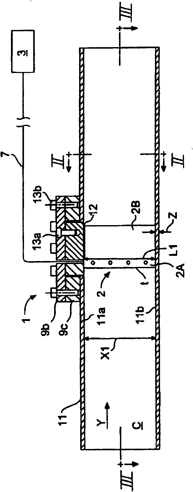
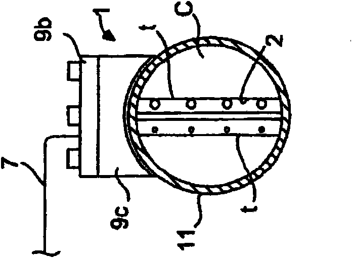
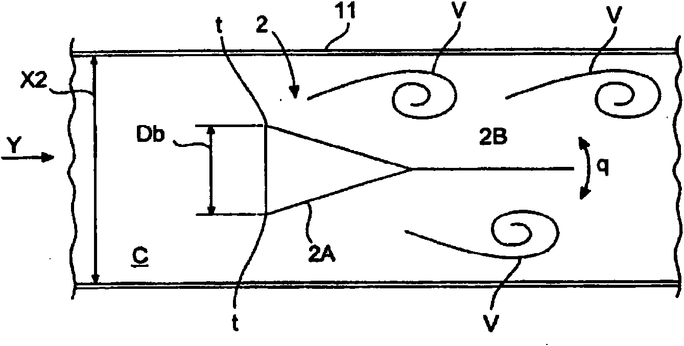
[0029] Figure 1-6 A non-limiting embodiment of an assembly comprising a fluid channel C and a flow meter 1 is shown.

[0030] Fluid channel C (for example, fluid line, fluid tube, fluid channel (fluid line / pipe / conduit) can be configured to guide fluid, for example, gas, gas mixture, air, liquid, liquid mixture, water, steam. In particular In the embodiment, the channel C may be configured to inject fluid into an oil or gas field, however, the skilled person will understand that the channel C may be used in many other applications. In this embodiment, the channel C has a diameter (width ) a substantially circular cross-section of W. The skilled person will understand that the channel may also have a different configuration, for example have a rectangular or square cross-section, or a different cross-section.

[0031] The flow meter 1 is config...


PUM


Abstract

An assembly comprising a fluid channel and a flowmeter, the flowmeter (1) comprising at least one vortex shedder (2) extending in the channel (C), each vortex shedder (2) being configured to generate Karman vortices (V) in fluid flowing through the channel (C) during operation, wherein each vortex shedder (2) is provided with a first fiber Bragg grating (FBG) of a fiber Bragg grating sensor (3, 7, FBG), wherein a Karman vortex frequency (fe) of the vortices (V) generated by the vortex shedder (2) is detectable utilizing a fiber Bragg grating (FBG) sensor signal relating to the respective first fiber Bragg grating (FBG) of that vortex shedder (2).

Description

technical field [0001] The invention relates to an assembly including a fluid channel and a flow meter, and a method of measuring fluid flow rate. Background technique [0002] In oil / gas wells, water or steam is often injected into the oil / gas field to increase production. Would like to provide information on flow conditions in available water / steam injection lines. However, only a limited number of flow meters are available for downhole applications, all of which are very expensive, bulky and complex (see eg the system described in US Pat. No. 6,691,584 B2). [0003] Furthermore, JP200387451 (Hishida Yasyuyki) describes an optical flow velocity sensor in which a fiber Bragg grating is used to detect flow induced bending of a flexible detection rod bent in the direction of flow. This configuration makes it relatively difficult to calibrate such a sensor, since the dependence between bending and flow velocity is non-linear, and additionally requires an additional Bragg gra...

Claims


Application Information

Patent Timeline
Patent Type & Authority Applications(China)
IPC IPC(8): G01F1/32
CPCG01F1/3263G01F1/3218G01F15/022G01F1/3266
Inventor 郑伦佳马里纳斯·卡洛勒斯·阿德里安努什·玛利亚·彼得斯沃特·希费尔利
Owner NEDERLANDSE ORG VOOR TOEGEPAST NATUURWETENSCHAPPELIJK ONDERZOEK TNO
Why Eureka
Try Eureka