Eureka AIR delivers breakthrough ideas for toughest innovation challenges, trusted by R&D personnel around the world.

Touch flat-panel display

一种平板显示器、触控的技术,应用在静态指示器、仪器、电数字数据处理等方向,能够解决影响被触电极判断等问题,达到提高准确性的效果

Inactive Publication Date: 2010-01-27
SOLUTION DEPOT LTD
View PDF1 Cites 55 Cited by
  • Summary
  • Abstract
  • Description
  • Claims
  • Application Information

AI Technical Summary

Problems solved by technology

The row and column electrodes of the flat-panel display cross to form a grid, and the touch excitation signal applied to one electrode will flow between the grid-shaped electrodes of the flat-panel display, thus affecting the judgment of the touched electrode

Method used


Image

  • Touch flat-panel display
  • Touch flat-panel display
  • Touch flat-panel display

Examples


specific Embodiment approach 1

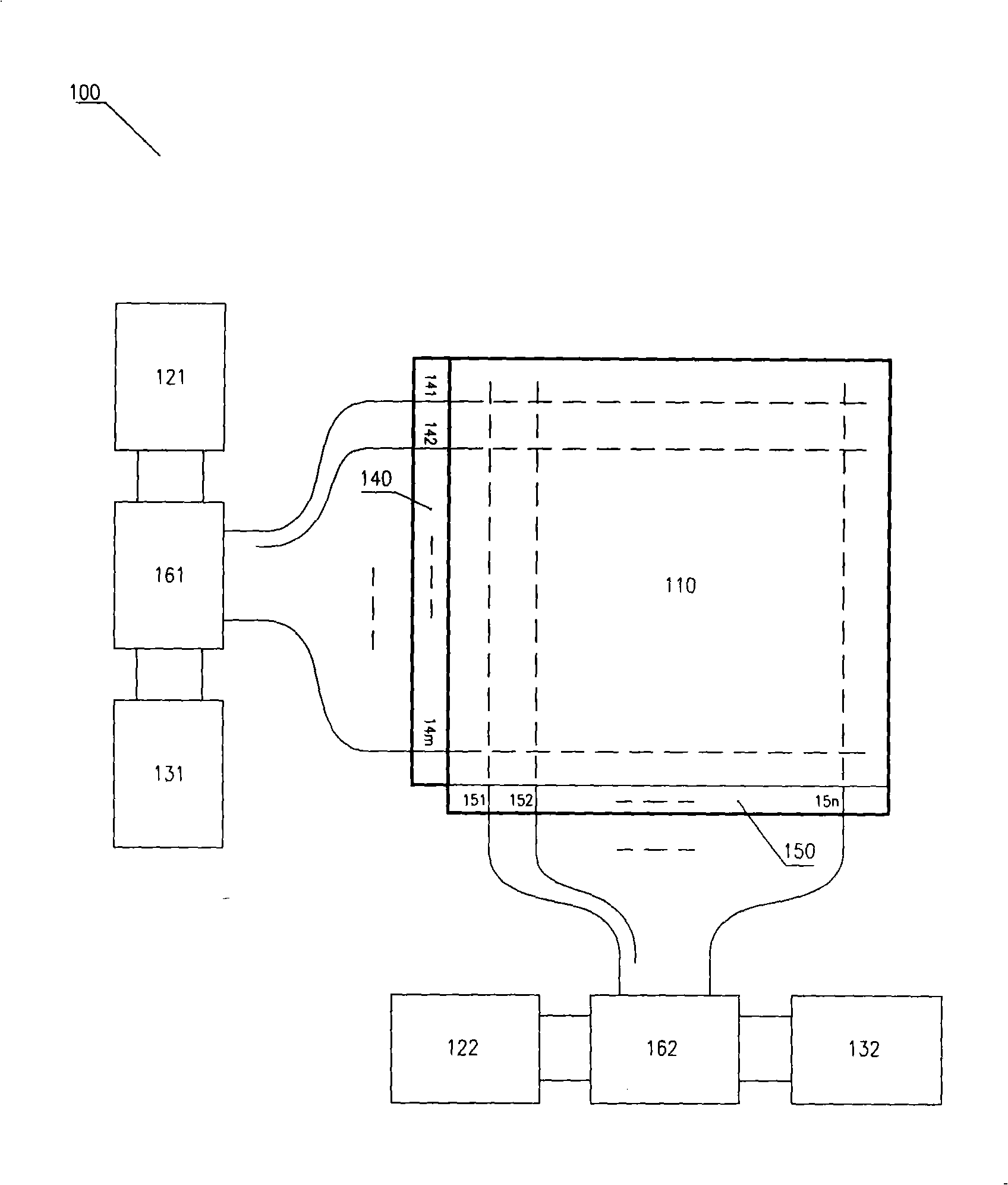
[0038] Such as figure 1 The shown touch panel display 100 includes a passive display screen 110, a display row driving circuit 121 and a display column driving circuit 122, a touch row detection circuit 131 and a touch column detection circuit 132, a row gating circuit 161 and a column gating circuit 162 and so on. The display screen 110 has a row electrode group 140 (with row electrode lines 141, 142, . . . , 14m), and a column electrode group 150 (with column electrode lines 151, 152, . . . , 15n). The row electrode group 140 of the display screen 110 is connected to both the display row driver circuit 121 and the touch row detection circuit 131 , and the column electrode group 150 is connected to both the display row driver circuit 122 and the touch row detection circuit 132 . The row gating circuit 161 and the column gating circuit 162 in the touch-sensitive flat panel display make the display screen electrodes communicate with the display driving circuit to transmit disp...

specific Embodiment approach 2

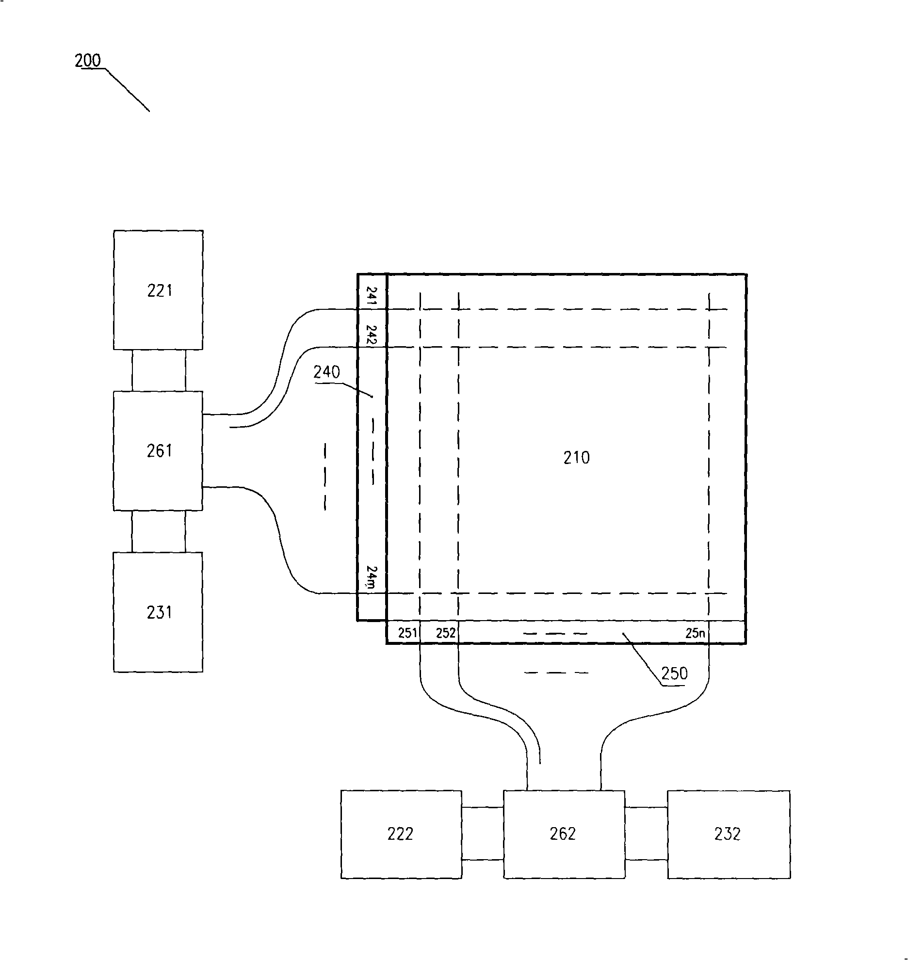
[0046] Such as figure 2 The shown touch panel display 200 includes a passive display screen 210, a display row driving circuit 221 and a display column driving circuit 222, a touch row detection circuit 231 and a touch column detection circuit 232, a row signal loading circuit 261 and a column Signal loading circuit 262 and so on. The display screen 210 has a row electrode group 240 (with row electrode lines 241, 242, . . . , 24m), and a column electrode group 250 (with column electrode lines 251, 252, . . . , 25n). The row electrode group 240 of the display screen 210 is connected to the display row driver circuit 221 and the touch row detection circuit 231 through the row signal loading circuit 261, and the column electrode group 250 is connected to the display column driver circuit 222 and the touch row detection circuit through the column signal loading circuit 262. 232. The signal loading circuit in the touch panel display enables the electrodes of the display screen t...

specific Embodiment approach 3

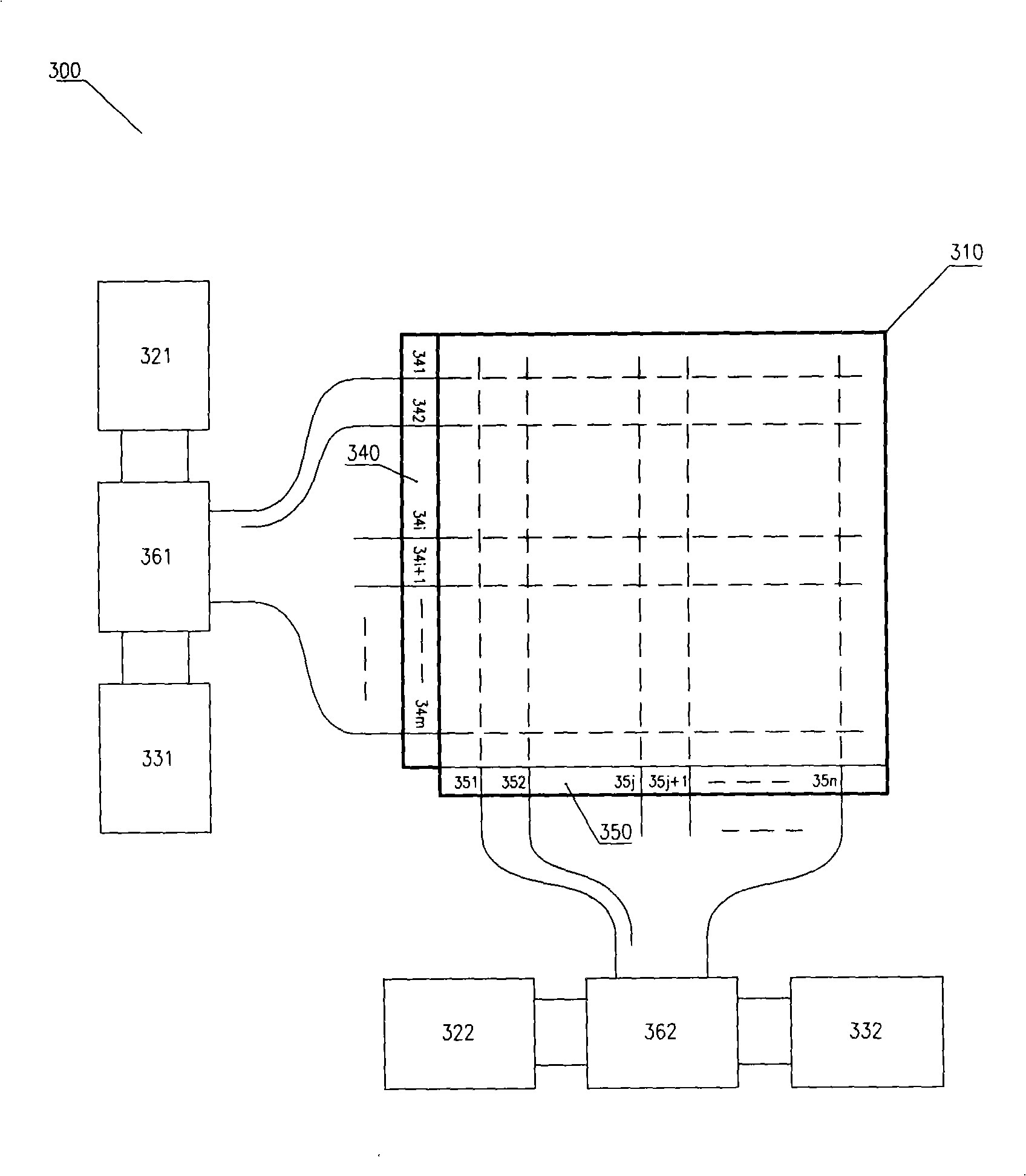
[0052] Such as image 3The shown touch panel display 300 includes a passive display screen 310, a display row driving circuit 321 and a display column driving circuit 322, a touch row detection circuit 331 and a touch column detection circuit 332, a row gating circuit 361 and a column gating circuit 362 and so on. Display screen 310 has row electrode group 340 (with row electrode lines 341, 342, ..., 34i, 34i+1, ..., 34m), and column electrode group 350 (with column electrode lines 351, 352, ..., 35j, 35j+ 1, ..., 35n). The row electrode group 340 of the display screen 310 is connected to both the display row driver circuit 321 and the touch row detection circuit 331 , and the column electrode group 350 is connected to both the display row driver circuit 322 and the touch row detection circuit 332 . The row gating circuit 361 and the column gating circuit 362 in the touch-sensitive flat panel display make the display screen electrodes communicate with the display driving cir...


PUM


Abstract

The invention discloses a touch flat-panel display, which comprises a display screen, a display driving circuit, a touch detection circuit and the like. Related circuits in the touch flat-panel display enable a display screen electrode to transmit a display driving signal and a touch signal, and the flat-panel display can be used for normal display and used for realizing touch detection through adisplay driving and touch detection multiplexing display screen electrode. By applying touch signals to a detected electrode and a non-detected electrode at the same time, the flow of the touch signals between the detected electrodes and between the detected electrode and the non-detected electrode is reduced, the flowing direction of the touch signals is controlled, and the accuracy of judgment on the touched electrodes is improved. By applying the touch signals to a plurality of groups of detected electrodes at the same time and respectively detecting the changes of the touch signals flowing through the groups of detected electrodes, less time is required for detecting touch points of the whole display screen.

Description

technical field [0001] The invention relates to a touch screen and a flat panel display, in particular to a touch type flat panel display. Background technique [0002] Current capacitive touch screens can be divided into two types: digital and analog. The digital capacitive touch screen is composed of two layers of electrodes with multiple parallel electrodes on each layer, and the two layers of electrodes are orthogonal to each other. A touch excitation signal is applied to each electrode. When a human finger touches the touch screen, the finger forms a coupling capacitance with certain electrodes on the touch screen, and a leakage current flows from the coupling capacitance. The touch detection circuit determines the touch position by detecting the leakage current and determining the two orthogonal electrodes forming a coupling capacitance with the finger on the two layers of electrodes. This method is only suitable for coarser positioning. When fine positioning is requ...

Claims


Application Information

Patent Timeline
Patent Type & Authority Applications(China)
IPC IPC(8): G06F3/041G09G3/20
CPCG06F3/0412G06F3/044G06F3/0416G06F3/04166G06F3/0446
Inventor 陈其良刘海平陈梅英
Owner SOLUTION DEPOT LTD
Why Eureka
Eureka Blog
Learn More