Use method of outer rotor reluctance motor, optical-mechanical-electrical integrated control system and three-phase alternating current

A reluctance motor and outer rotor technology, applied in the direction of a single motor speed/torque control, electromechanical devices, electrical components, etc., can solve the problem of failure to retrieve the hidden pole outer rotor reluctance motor, not found, etc.

Inactive Publication Date: 2010-01-27
张玉宝
View PDF0 Cites 13 Cited by
  • Summary
  • Abstract
  • Description
  • Claims
  • Application Information

AI Technical Summary

Problems solved by technology

But so far, the invention of the hidden pole type external rotor reluctance motor has not been retrieved, and no method of using a three-phase AC power supply to start the two-phase or three-pha

Method used


Image

  • Use method of outer rotor reluctance motor, optical-mechanical-electrical integrated control system and three-phase alternating current
  • Use method of outer rotor reluctance motor, optical-mechanical-electrical integrated control system and three-phase alternating current
  • Use method of outer rotor reluctance motor, optical-mechanical-electrical integrated control system and three-phase alternating current

Examples


Embodiment Construction

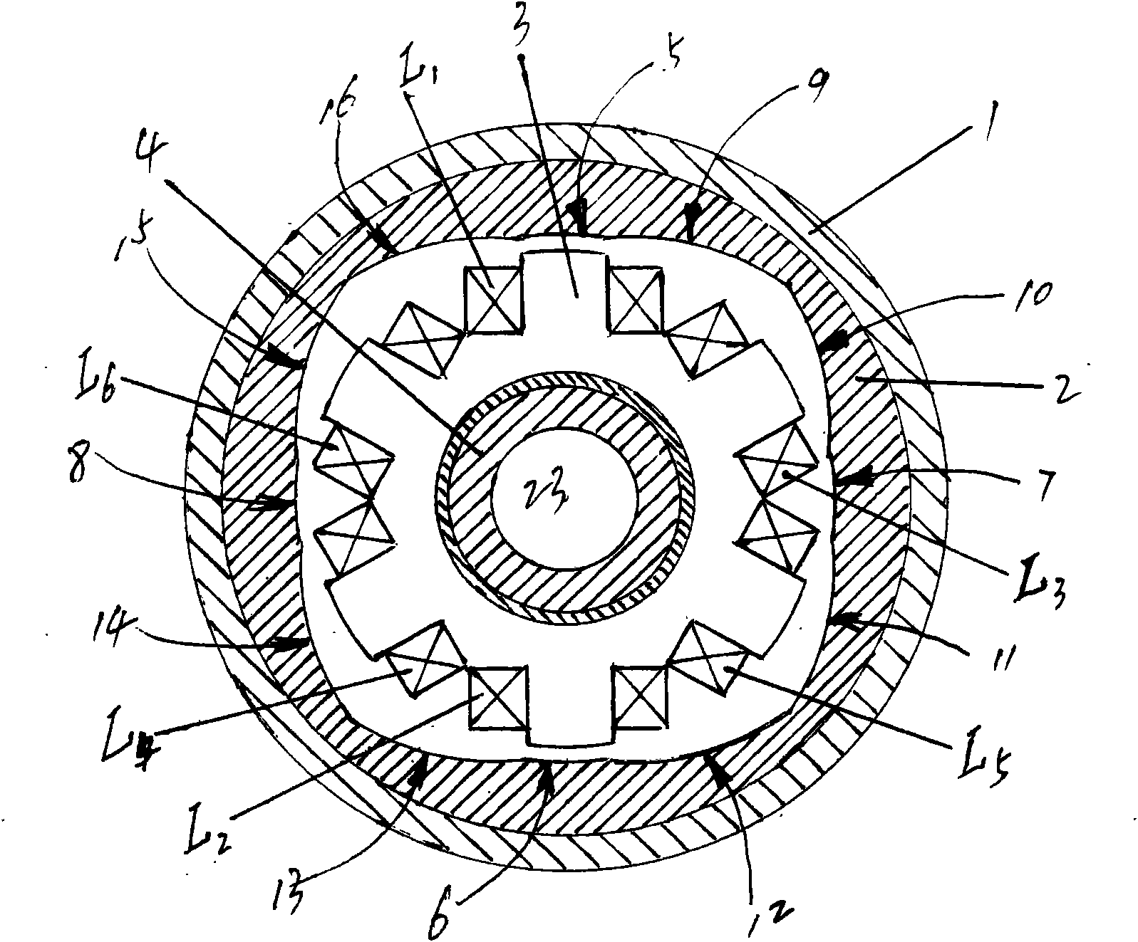
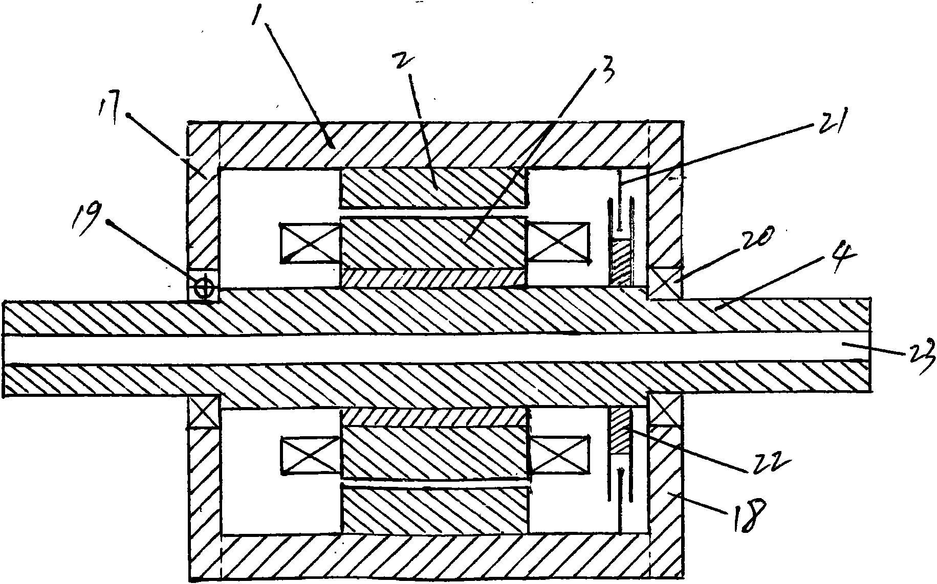
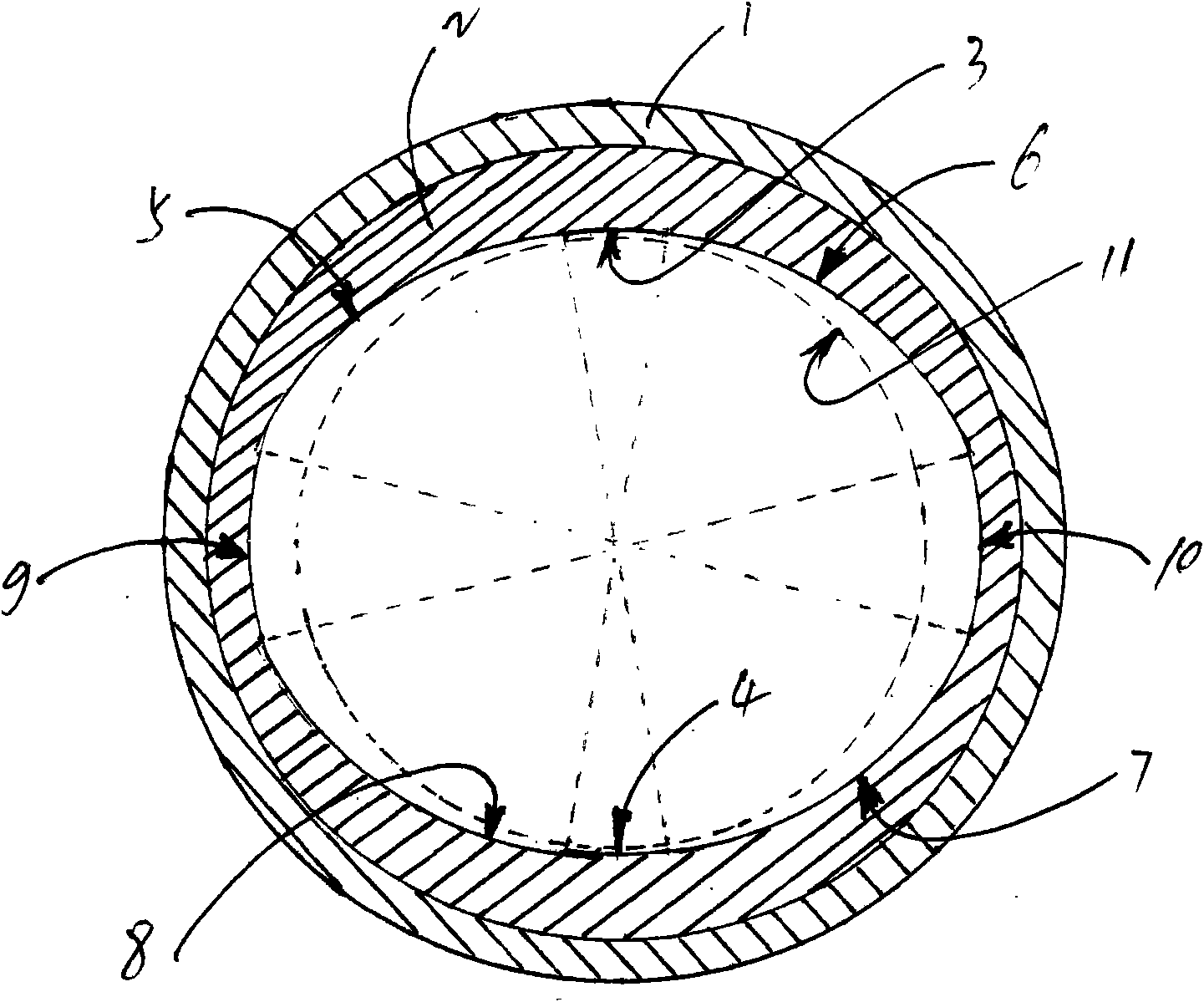
[0027] according to figure 1 , figure 2 As shown, this is an outer rotor reluctance motor with a three-phase 6 / 4 pole stator and rotor structure, and its stator core 3 contains six magnetic poles, which are distributed equidistantly on the circumference. The right-angle dedendum width of each stator magnetic pole is equal to the opening of the six magnetic poles on the circumference of 12 equally divided angles. A simple concentrated winding is installed on each stator pole, and the windings on the two radially opposite stator poles are connected in series or in parallel to form the same phase. That is: the L 1 and L 2 Form A phase, L 3 and L 4 Form C phase, L 5 and L 6 Phase B is formed, and then two pairs of concentric inner arc surfaces (5, 6 and 7, 8) that are radially opposite, have the same radius, are equal in arc width to the stator pole surface, and have a diameter slightly larger than the maximum diameter of the stator pole, respectively Through a plurality ...


PUM


Abstract

The invention discloses a use method of an outer rotor reluctance motor, an optical-mechanical-electrical integrated control system and three-phase alternating current, which comprises the following steps: connecting and transiting two inner concentric cambered surfaces to two concentric arcs with larger diameters respectively through two eccentric arcs respectively so as to form a bipolar non-salient pole type outer rotor core, wherein the two inner concentric cambered surfaces are radially opposite to each other, have the same semidiameter and equal arc lengths, and are not more than the angle amount occupied on the circumference by a stator magnetic pole, and the diameter of the two inner concentric cambered surfaces is slightly larger than the maximum diameter of the stator magnetic pole; making the rotary cooperation between the inner cambered surface of the magnetic pole of the outer rotor core and the outer cambered surface of each stator magnetic pole to completely satisfy the requirement that a working air gap changes gradually in a descending order; then forming a movable connection through an end cover of the motor, a bearing and a hollow dead axle for mounting and fixing the stator core; forming all the motion mechanism of the outer rotor reluctance motor; and adopting an opto-coupler automatic switch for control. Thus, the method is particular suitable for use on a two-wheel electric motorcycle. The invention also relates to a method for directly starting a two-phase outer rotor reluctance motor and a two-phase reluctance motor by using three-phase alternating current.

Description

Technical field: [0001] The invention relates to an outer rotor reluctance motor, in particular to the inner multi-arc connection of the outer rotor of the reluctance motor. The invention also relates to an optical-mechanical-electrical integration control system of the outer rotor reluctance motor. The invention also relates to a method for starting and running a reluctance motor using three-phase alternating current. Background technique: [0002] The reluctance motors in the prior art all adopt a double salient pole stator and rotor structure. Simple concentrated windings are installed on the stator poles and the windings on the two radially opposite stator poles form the same phase. Use the switch-type DC power supply method and continuously switch on and off the current of the stator windings of the corresponding phases in a certain order to control the forward and reverse running directions of the internal working magnetic field of the reluctance motor, and rely on t...

Claims


Application Information

Patent Timeline
IPC IPC(8): H02K29/00H02K29/10H02P6/16H02P6/08
Inventor 张玉宝
Owner 张玉宝
Why Eureka
Try Eureka