Supercharge Your Innovation With Domain-Expert AI Agents!

Electronic equipment for flow control

A technology of electronic equipment and flow control, applied in the field of electronics, can solve the problems of user inconvenience and the ineffectiveness of electronic community.

Inactive Publication Date: 2010-01-27
张路洲
View PDF0 Cites 0 Cited by
  • Summary
  • Abstract
  • Description
  • Claims
  • Application Information

AI Technical Summary

Problems solved by technology

But this kind of electronic communication is not very effective, which brings inconvenience to users.

Method used


Image

  • Electronic equipment for flow control
  • Electronic equipment for flow control
  • Electronic equipment for flow control

Examples


Embodiment Construction

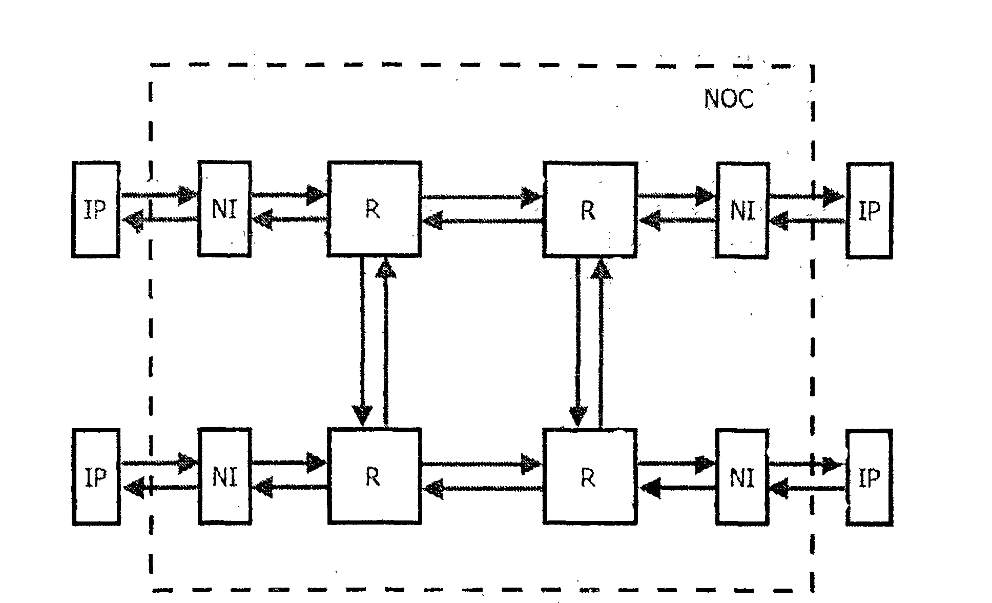
[0013] The invention comprises a processing unit, interconnection means for coupling the processing unit, and a plurality of interface means, arranged between the processing unit and the interconnection means, for enabling communication between the processing unit and the interconnection means. Communication between the processing units is packet based communication via interface means and interconnection means. The interface means includes a flow control means for controlling the flow of communication between the two processing units based on the flow control credit information.

[0014] If necessary, more credit information can be inserted into the communication so that sufficient credit information can be introduced.

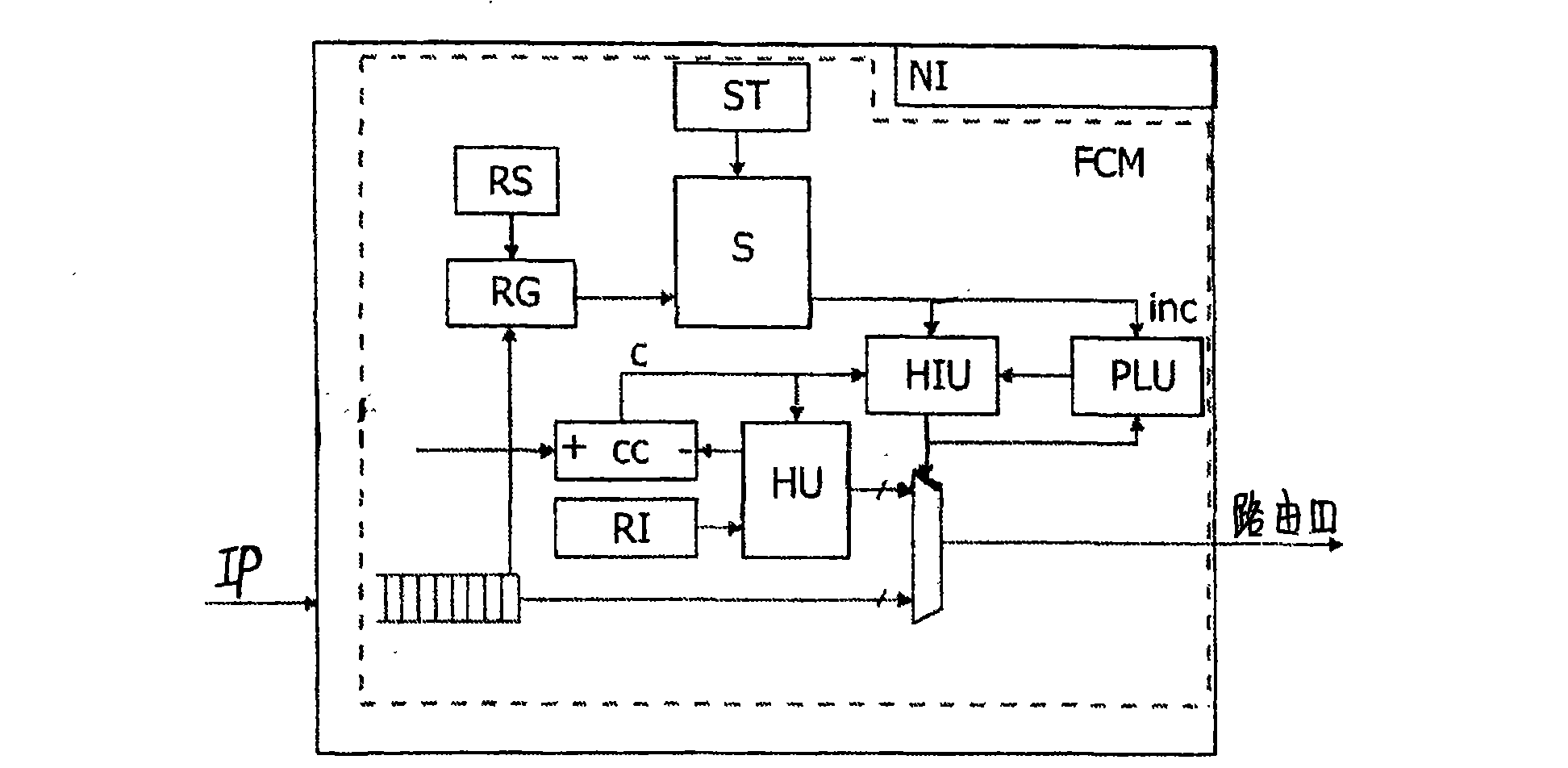
[0015] The interface means includes a time slot table with flow control information. Accordingly, flow control is performed dynamically and can better match the actual requirements of the communication.

[0016] Such as figure 1 As shown, multiple IP block...


PUM


Abstract

The invention relates to electronic equipment for flow control, which belongs to the field of electronics and can be used for flow control more effectively. The electronic equipment for flow control is characterized by comprising processing units, an interconnecting device for coupling the processing units and a plurality of interface devices arranged between the processing units and the interconnecting device for enabling the processing units and the interconnecting device to communicate. The communication between the processing units is based on data packets through the interface devices and the interconnecting device. Each of the interface devices comprises a flow control device for controlling communication flows between two processing units based on flow control credit information.

Description

Technical field: [0001] The invention belongs to the field of electronics and relates to an electronic device for flow control. Background technique: [0002] An IP block is an intellectual property block, usually an on-chip module with specific functions. The IP blocks communicate with each other through the on-chip network. A network-on-chip is a scalable interconnect structure; a network-on-chip typically consists of network interfaces and routers. The network interfaces are used to provide an interface between the IP block and the Network on Chip, ie they translate information from the IP block into information understandable by the Network on Chip and vice versa. The router is used to transfer data from one network interface to another network interface. For best effort communication, there is no guarantee of latency regarding communication throughput. For guaranteed throughput services, an exact value for latency and throughput is required. Communication within th...

Claims


Application Information

Patent Timeline
Patent Type & Authority Applications(China)
IPC IPC(8): H04L12/56H04L12/02H04L12/801
Inventor 张路洲
Owner 张路洲
Features
  • R&D
  • Intellectual Property
  • Life Sciences
  • Materials
  • Tech Scout
  • Unparalleled Data Quality
  • Higher Quality Content
  • 60% Fewer Hallucinations
Learn More