Alternating optical system: mixing and matching optics to maximize binocular visual benefits

A binocular vision and binocular technology, applied in the field of vision correction and ophthalmology lenses, can solve the problems of patients with unsatisfactory binocular vision

Inactive Publication Date: 2010-01-27
ALCON RES LTD
View PDF4 Cites 8 Cited by
  • Summary
  • Abstract
  • Description
  • Claims
  • Application Information

AI Technical Summary

Problems solved by technology

Since many patients prefer binocular vision, such neglect in IOL selection may result in patients with less than ideal binocular vision

Method used


Image

  • Alternating optical system: mixing and matching optics to maximize binocular visual benefits
  • Alternating optical system: mixing and matching optics to maximize binocular visual benefits
  • Alternating optical system: mixing and matching optics to maximize binocular visual benefits

Examples


Embodiment 1

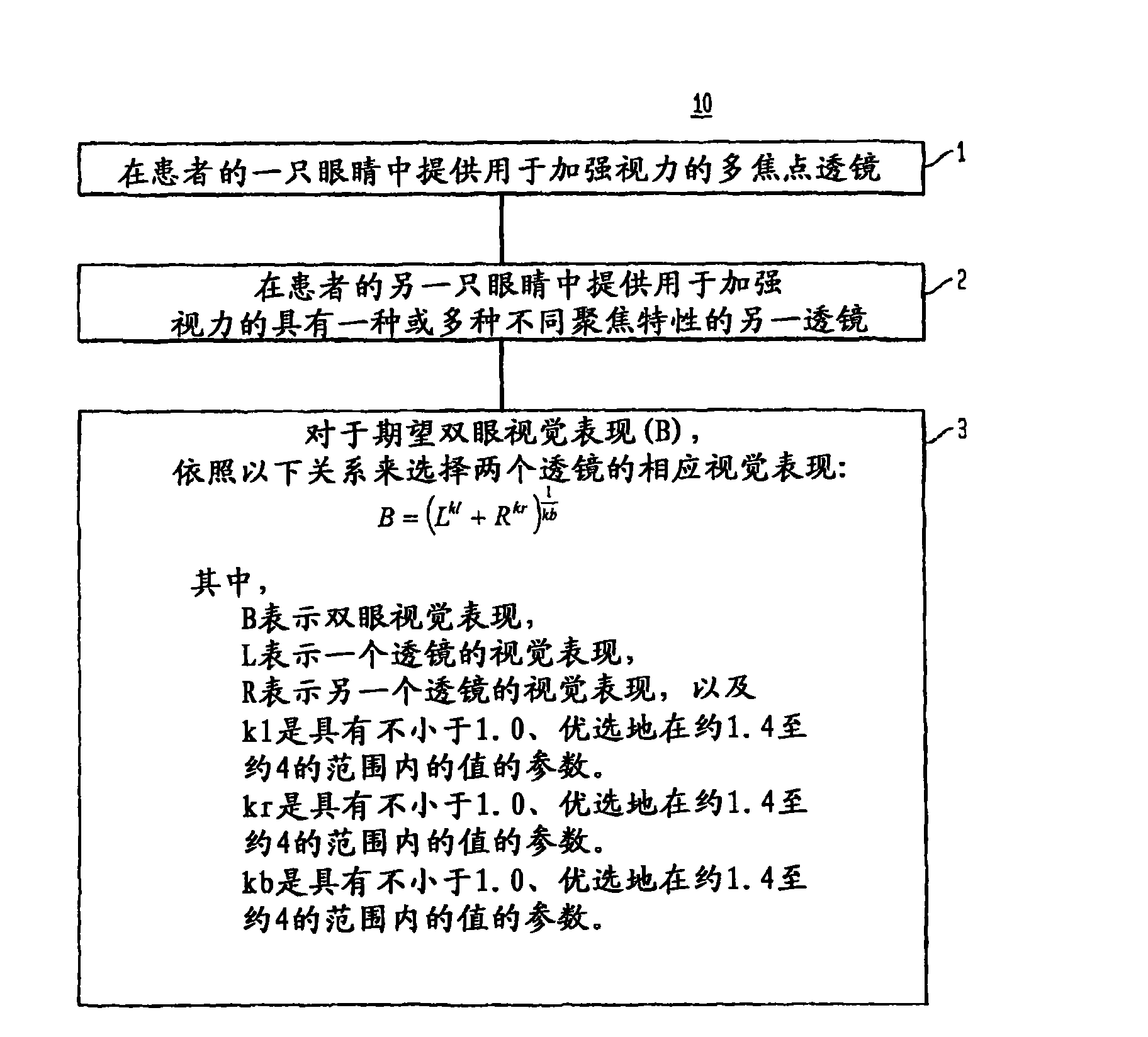
[0134] [066] A multifocal lens featuring a target refractive power of 0D and an added power of +3.0D was provided for use in one eye of the patient. Figure 7A The calculated through-focus acuity curve A (Acuity as a function of defocus) associated with this lens is shown. Visual acuity was expressed as the logarithm of the minimum angle of resolution (MAR in armin). A monofocal lens with a target power of -1.5D was provided for use in the patient's other eye. It is assumed that this lens exhibits some degree of asphericity (ie a conic constant of -42) in one of its surfaces to reduce spherical aberration effects. Figure 7A The calculated through-focus visual acuity associated with this single focus lens is also presented as Curve B. Predicted binocular visual performance characterized by binocular out-of-focus visual acuity curves was calculated by utilizing equation (1) above and setting parameters kl, kr, and kb to 4. This binocular acuity curve (shown by the dashed lin...

Embodiment 2

[0136] [067] A multifocal lens featuring a target refractive power of 0D and an added power of +3.0D was provided for use in one eye of the patient. Figure 7B The calculated through-focus acuity curve A (Acuity as a function of defocus) associated with this lens is shown. Another multifocal lens with a target power of 1D and an added power of 2.5D was provided for use in the patient's other eye. Figure 7B The calculated through-focus visual acuity associated with this other multifocal lens is also presented (curve B). Predicted binocular visual performance characterized by binocular out-of-focus visual acuity curves was calculated by utilizing equation (1) above and setting parameters kl, kr, and kb to 4. This binocular acuity curve (curve C shown by the dashed line) illustrates that the combined lens provides better than about 20 / 30 visual acuity from infinity to a distance of about 30 cm.


PUM


Abstract

In one aspect, the present invention provides a method for correcting vision that employs two lenses, at least one of which is a multifocal lens, with different focusing characteristics for use in the two eyes of the patient. The visual performance of each lens (e.g., visual contrast or acuity) is selected in accordance with a predefined relation so as to optimize the binocular visual performance provided by the combination of the lenses.

Description

technical field [0001] [001] The present invention relates generally to methods and ophthalmic lenses for correcting vision, and more particularly to such a method of providing enhanced binocular vision. Background technique [0002] [002] Vision is often corrected with ophthalmic lenses, such as intraocular lenses (IOLs). For example, an IOL may be implanted in a patient's eye to replace, or in some cases augment, the patient's natural lens. Typically, such IOLs are selected without regard to the visual performance of the patient's other eye, which may retain its crystalline lens or have another IOL. Since many patients prefer binocular vision, such neglect in selecting an IOL may result in less than ideal binocular vision for the patient. [0003] [003] Accordingly, there is a need for an enhanced method for correcting a patient's vision, and in particular a method and associated ophthalmic lens that will provide the patient with improved binocular vision, as most patien...

Claims


Application Information

Patent Timeline
Patent Type & Authority Applications(China)
IPC IPC(8): G02C7/04A61F2/16
CPCG02C7/04G02C2202/20G02C7/028A61F2/16G02C7/027A61F2/1621A61F2/1648A61F2/1613
Inventor 洪昕M·卡拉克雷张晓啸A·布拉德利
Owner ALCON RES LTD
Why Eureka
Try Eureka