Optical communication base station, optical signal conversion apparatus, and optical signal conversion method

A technology of a communication device and a conversion device, which is applied in the direction of selection device, multiplexing communication, selection device of multiplexing system, etc., can solve the problems of unresearched, expensive circuit, and mixed existence of terminals on the side of users who are difficult to join.

Inactive Publication Date: 2010-01-27
FUJITSU LTD
View PDF1 Cites 5 Cited by
  • Summary
  • Abstract
  • Description
  • Claims
  • Application Information

AI Technical Summary

Problems solved by technology

In the optical burst transponder, clock synchronization is introduced, and the circuits that can perform clock synchronization for received signals of different bit rates are expensive, and it is difficult to arrange the multiple circuits in the access network.
[0012] Moreover, for the communication in the uplink direction, studies have been made on the use of different bit rates among the subscriber-side terminals, but no research has been done on the use of different bit rates for the communication in the downlink direction, and it is difficult to mix subscriber-side terminals with different bit rates. exist

Method used


Image

  • Optical communication base station, optical signal conversion apparatus, and optical signal conversion method
  • Optical communication base station, optical signal conversion apparatus, and optical signal conversion method
  • Optical communication base station, optical signal conversion apparatus, and optical signal conversion method

Examples


Embodiment Construction

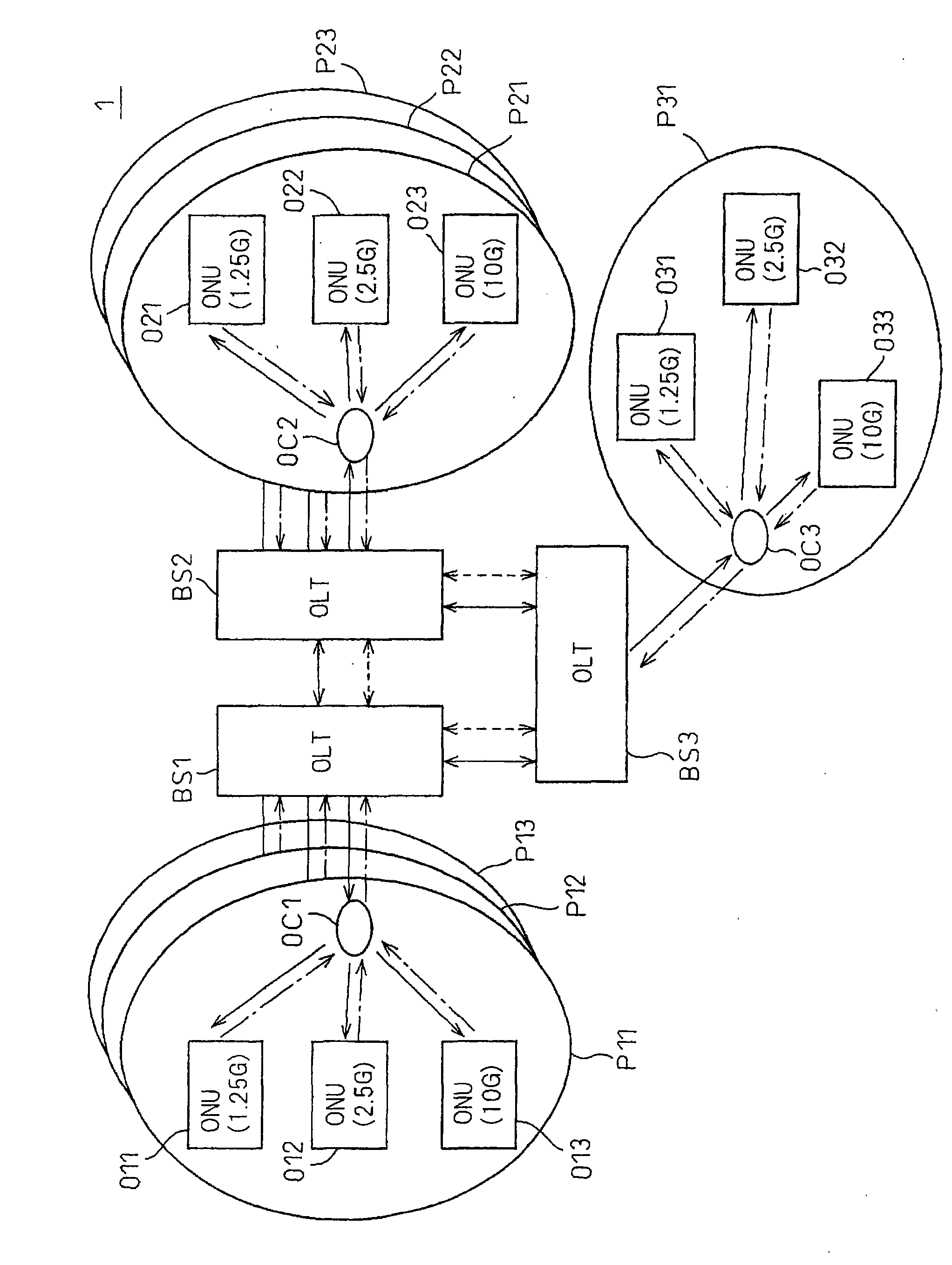
[0056] Hereinafter, embodiments of the present invention will be described with reference to the drawings. figure 2 It is a diagram showing a first configuration example of an optical communication system according to an embodiment of the present invention.

[0057] The optical communication system 1 is constituted by a plurality of base stations BS1 to BS3 and a PON system. The PON system connects the plurality of base stations BS1 to BS3 and subscriber terminals O11 to O13, O21 to O23 and subscriber terminals O11 to O13, O21 to O23 and O31~O33 are connected.

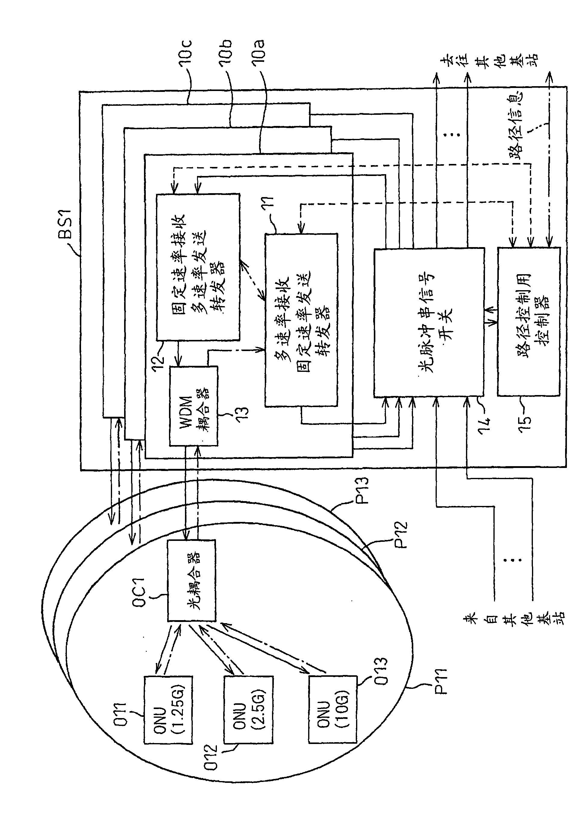
[0058] The base station BS1 is provided with a plurality of telephone office side terminals (OLT) of the PON systems P11 to P13. Similarly, the base station BS2 is equipped with a plurality of office-side terminal devices of the PON systems P21 to P23, and the base station BS3 is equipped with one office-side terminal device of the PON system P31.

[0059] Each PON system is provided with: a subscriber-side terminal...


PUM


Abstract

An optical communication base station (BS1) receives, from a plurality of subsidiary communication apparatuses (O11-O12), upstream optical signals having upstream bit rates specific to the respective subsidiary communication apparatuses (O11-O12), and transmits, to the subsidiary communication apparatuses (O11-O12), downstream optical signals having downstream bit rates specific to the respective subsidiary communication apparatuses (O11-O12). The optical communication base station (BS1) comprises a first optical signal converting unit (11) that changes the bit rates of the upstream optical signals to convert the upstream signals to inter-station optical signals of fixed bit rates to be received by receiving stations at the other end of communication (BS2,BS3), and a second optical signal converting unit (12) that changes, in accordance with the destinations of the subsidiary communication apparatuses (O11-O12), the bit rates of inter-station optical signals received from the transmitting stations at the other end of communication (BS2,BS3) to convert these inter-station optical signals to downstream optical signals.

Description

technical field [0001] The present invention relates to an optical access network system that uses an optical communication network to construct from a switching center of a communication company to a terminal of a subscriber. In particular, it relates to an optical access network system capable of changing the bit rate according to subscribers and transmitting uplink optical signals from subscribers to base stations in bursts. Background technique [0002] Various forms of optical access network systems have been proposed as next-generation optical access network systems that do not convert transmission signals into electrical signals but transmit transmission signals to subscriber-side terminals in the state of optical signals. As such an optical access system, there is, for example: an E-PON (Ethernet, registered trademark) corresponding to a B-PON (Broadband Passive Optical Network) corresponding to an ATM frame and an Ethernet (Ethernet, registered trademark) frame. (r...

Claims


Application Information

Patent Timeline
Patent Type & Authority Applications(China)
IPC IPC(8): H04B10/20H04B10/24H04J14/08H04B10/27H04B10/272H04B10/291H04B10/556
CPCH04B10/272H04J3/22H04Q2011/0064H04Q11/0067H04J3/1694
Inventor 甲斐雄高青木泰彦
Owner FUJITSU LTD
Why Eureka
Try Eureka