Drive system for a fitting

A technology of driving device and transmission device, applied in door/window accessories, wing parts, hinges with pins, etc., can solve the problems of laborious opening and closing of flip accessories, increase manufacturing costs, etc., and achieve the effect of reducing storage

Active Publication Date: 2010-03-24
HETTICH HEINZE GMBH & CO +1
View PDF1 Cites 6 Cited by
  • Summary
  • Abstract
  • Description
  • Claims
  • Application Information

AI Technical Summary

Problems solved by technology

This increases the manufacturing costs, since usually only a limited number of pieces of the specified drive fittings can be sold
Especially in the area of ​​flap fittings where probl

Method used


Image

  • Drive system for a fitting
  • Drive system for a fitting
  • Drive system for a fitting

Examples


Embodiment Construction

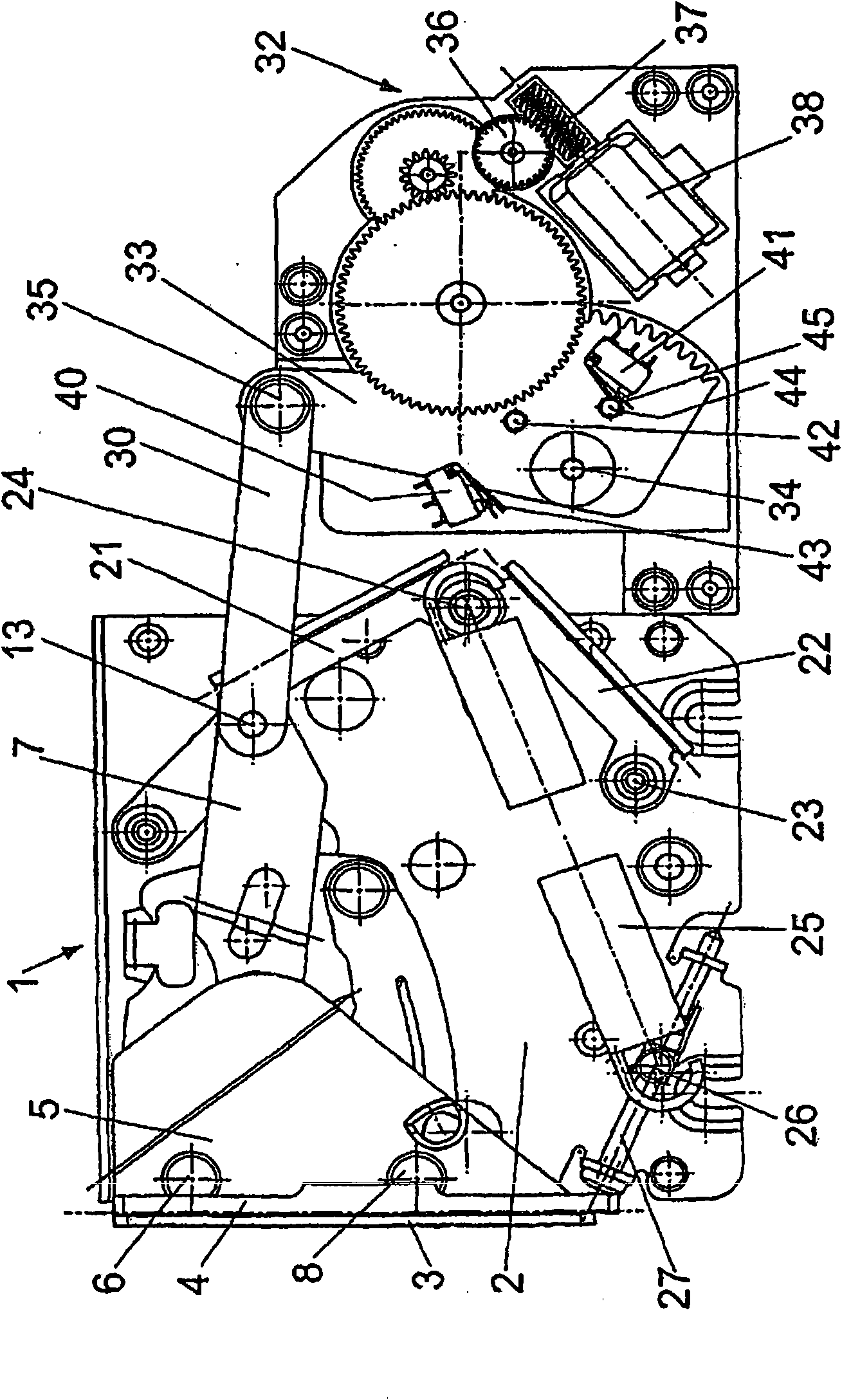
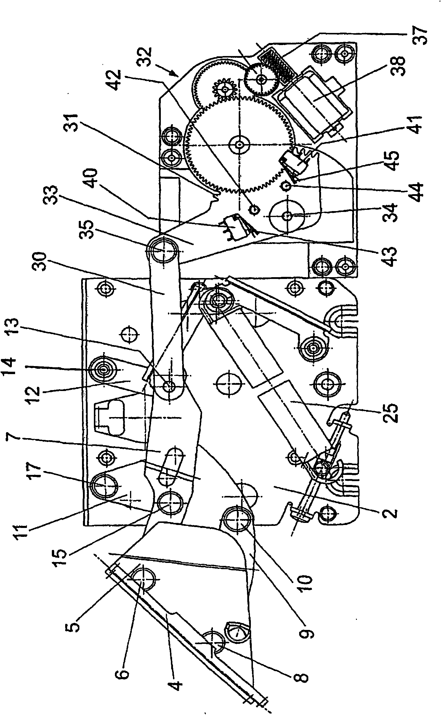
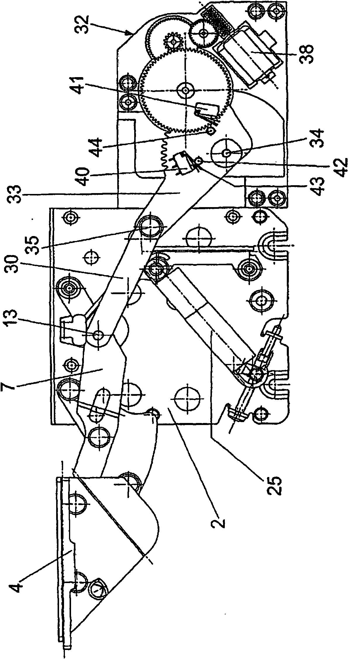
[0019] figure 1 shows a drive for a flap fitting 1 which is mounted or fixable via a fastening plate 2 on a furniture, preferably a cabinet. The flap fitting 1 comprises a pivot element 4 on which a plate 3 is arranged for connection to a flap. The rotary element 4 is angular and has, on a section 5 perpendicular to the plane of the plate 3 , an articulation axis 6 on which a guide lever 7 is mounted. A further shaft 8 is formed in the part 5 at a distance from the shaft 6 , on which a further guide lever 9 is rotatably mounted.

[0020] The end of the guide lever 9 remote from the rotary element 4 is connected via a shaft 10 to a first lever 11 , which is likewise hinged to the guide lever 7 on a shaft 15 . At a distance from the first lever 11 supported on a shaft 17 on the fixed plate 2, a second lever 12 is arranged, which is hinged on one side via a shaft 13 to the guide lever 7 and at the other end via a shaft 14. It is hingedly connected with the fixed plate 2.

[...


PUM


Abstract

A drive system for a fitting, in particular a flap hinge for cupboards, has a housing (50) that can be secured to the body of a piece of furniture. An electric motor (38) provided on or in the housing (50) drives by means of gears (32) a coupling element (30) linked to a portion (7) of the fitting. The coupling element (30) is centrally arranged in the housing (50), in a direction perpendicular to the plane of motion of the portion (7) of the fitting. The drive system can be mounted on opposite sides of the body of a piece of furniture for driving a flap hinge (1).

Description

technical field [0001] The invention relates to a drive device for fittings, in particular for flip fittings of cabinet furniture, comprising a housing that can be fixed on the furniture body, on or in which an electric motor is arranged, which drives a A coupling element that connects to an accessory element. Background technique [0002] There are fittings for furniture which are movable by means of an electric drive. For this purpose, the drive is usually individually adapted to the corresponding accessory element and designed for a particular purpose of use. This increases the manufacturing costs, since generally only a limited number of pieces of the specified drive fittings can be sold. In particular, where the area of ​​the flap fitting poses problems, a drive device is desirable, since the flap fitting is usually arranged vertically suspended in cabinet furniture and opening and closing the flap fitting is laborious. Contents of the invention [0003] It is ther...

Claims


Application Information

Patent Timeline
IPC IPC(8): E05D3/06E05F15/12
CPCE05Y2800/232E05Y2400/354E05Y2201/434E05Y2400/324E05Y2600/458E05Y2201/416E05Y2400/326E05D3/16E05Y2800/17E05Y2900/20E05F1/1276E05Y2800/174E05F15/127E05F15/63E05Y2600/41
Inventor O·舍尔U·索博勒夫斯基S·安德舒斯A·戈格斯T·尼迪克
Owner HETTICH HEINZE GMBH & CO
Why Eureka
Try Eureka