Optical illumination module

A lighting module and optical technology, applied in lighting devices, lighting and heating equipment, components of lighting devices, etc., can solve problems such as astigmatism and inability to obtain beams, and achieve the goal of increasing light-gathering ability, improving luminous intensity and uniformity. Effect

Inactive Publication Date: 2010-02-03
GENIUS ELECTRONICS OPTICAL CO LTD
View PDF0 Cites 1 Cited by
  • Summary
  • Abstract
  • Description
  • Claims
  • Application Information

AI Technical Summary

Problems solved by technology

But in fact, when a spherical convex lens is used, a completely parallel beam cannot be obtained, and astigmatism will still appear after the light source is refracted

Method used


Image

  • Optical illumination module
  • Optical illumination module
  • Optical illumination module

Examples


Embodiment Construction

[0019] The following is a further detailed description in conjunction with the drawings of the preferred embodiments of the present invention, so as to enable those familiar with the related art of the present invention to implement the technical solutions of the present invention according to the description of this specification.

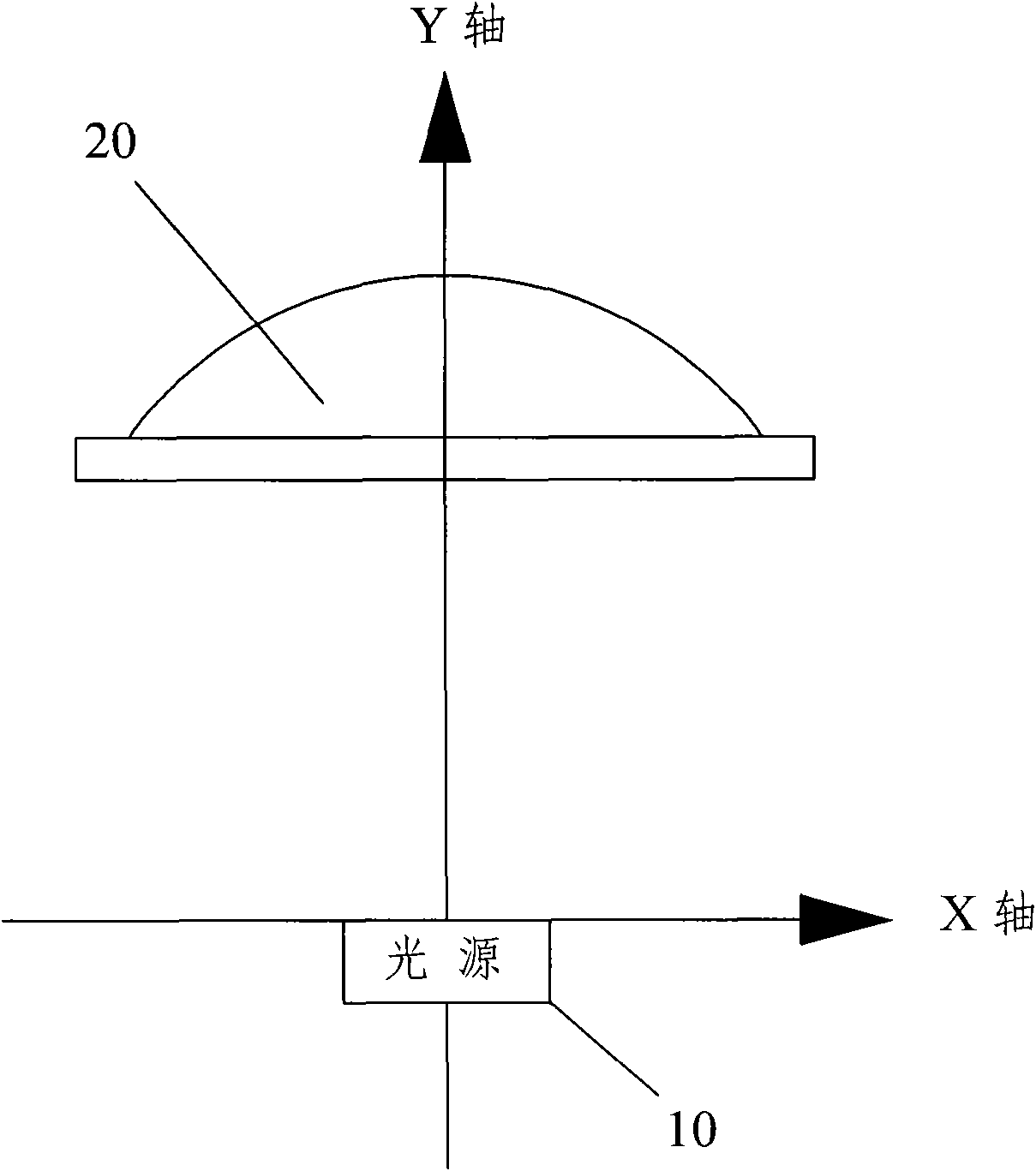
[0020] First, like figure 1 Shown is a preferred embodiment of the optical lighting module of the present invention, which includes:

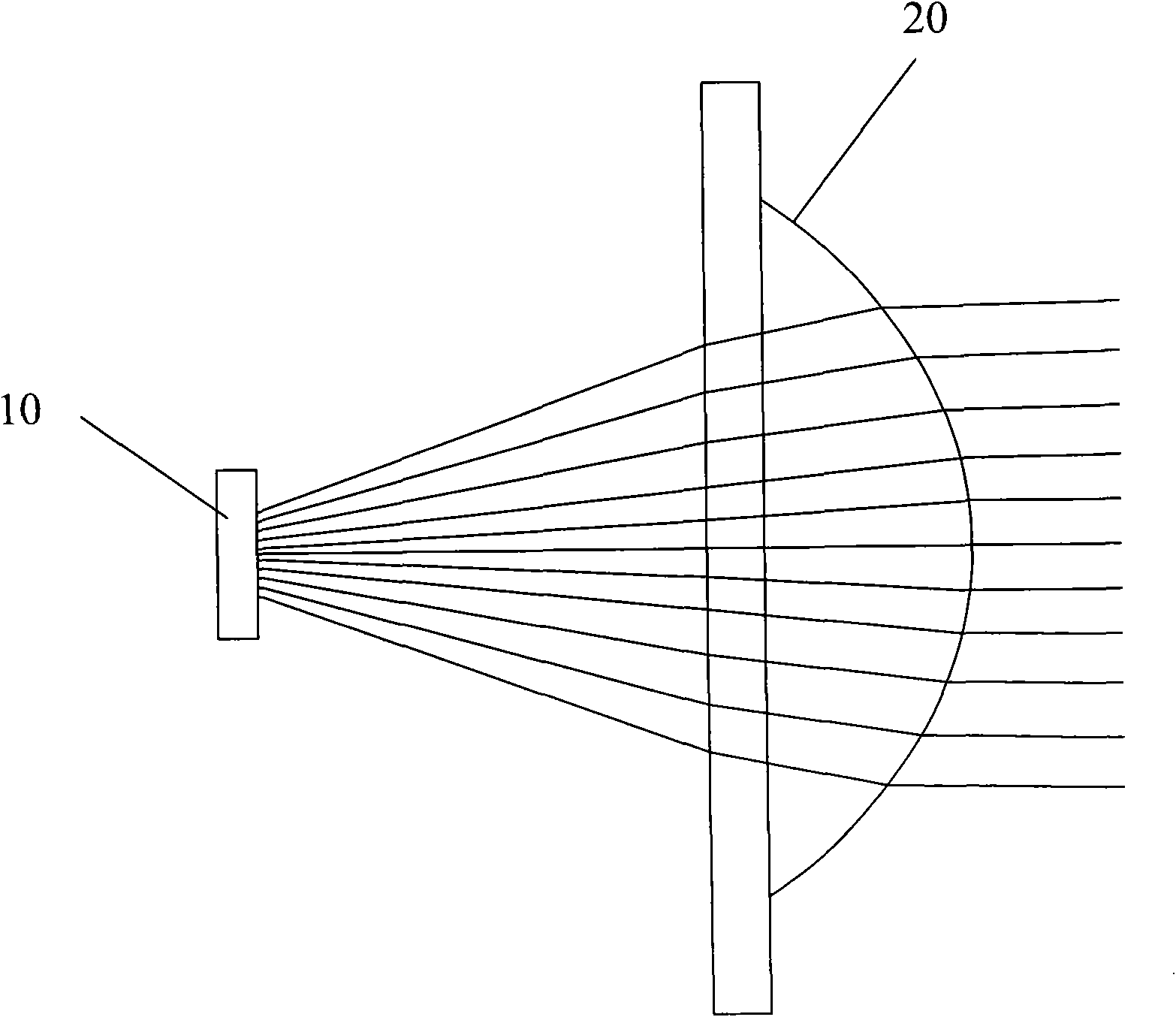
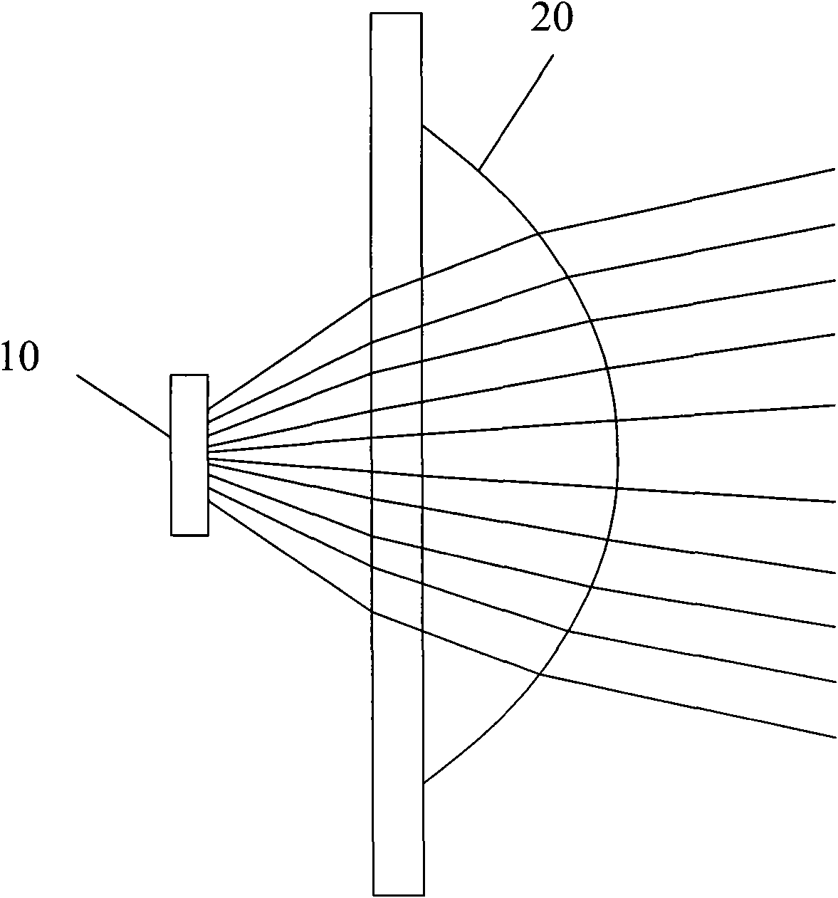
[0021] The fixed light source 10 is a light-emitting diode, and a plano-convex lens 20 is arranged at a specific distance in the optical axis direction. The aforementioned specific distance refers to a distance between 13.5 mm or more and 16.3 mm or less, and the distance is defined as the light-emitting surface of the fixed light source 10 to The distance of the apex of the convex surface of the plano-convex lens 20;

[0022] The plano-convex lens 20 is a rotationally symmetrical aspheric lens. Its flat end is used as th...


PUM


Abstract

The invention relates to an optical illumination module, which comprises a fixed light source and a plano-convex lens, wherein the fixed light source is a light-emitting diode; the plano-convex lens is an aspheric lens in rotary symmetry, and is arranged within a specific distance more than or equal to 13.5 millimeters and less than or equal to 16.3 millimeters in an optical axis direction of thefixed light source; and a plane end of the plano-convex lens is a light beam incident surface, while a convex end is a light beam emergent surface. When the fixed light source is arranged at a coordinate origin, a convex curve of the plano-convex lens is formed by serially connecting a series of points with specific coordinate values; and when the plano-convex lens displaces in the specific distance, the light source can refract an illumination angle to the minimum so as to achieve the aim of improving illumination intensity and prolonging illumination distance.

Description

Technical field [0001] The present invention mainly relates to an optical lighting module, in particular to an optical lighting module which is applied to a flashlight or various lighting fixtures and can generate light beams with an optimal angle. Background technique [0002] Related well-known structures in the prior art, such as the "full-surface concentrating flashlight" with Taiwan Patent No. 568245: a full-surface concentrating flashlight, which includes a flashlight body, a lamp holder, a lampshade set and a high transmittance The flashlight is composed of a high-speed optical body. The flashlight system has a battery canister for accommodating the battery. The lamp holder is a device for implanting and guiding the light-emitting element, and is accommodated at the front end of the flashlight body, and the lampshade is assembled The lampshade device for protecting the lamp holder and the light-emitting assembly at the front end of the flashlight body is characterized by: ...

Claims


Application Information

Patent Timeline
IPC IPC(8): F21V5/04F21Y101/02F21Y115/10
Inventor 何彦纬
Owner GENIUS ELECTRONICS OPTICAL CO LTD
Why Eureka
Try Eureka