Method and system for measuring aspiratory flow velocity by differential pressure type sensor

A sensor and differential pressure technology, which is applied in the field of measuring inspiratory flow rate using a differential pressure sensor, can solve the problems of weak output signal, complicated implementation, and narrowed measurement range, so as to reduce inspiratory resistance and be simple and easy to implement , reducing the effect of breathing

Inactive Publication Date: 2010-02-10
BEIJING AEONMED
View PDF0 Cites 5 Cited by
  • Summary
  • Abstract
  • Description
  • Claims
  • Application Information

AI Technical Summary

Problems solved by technology

However, when measuring at low flow rates, the output signal of the sensor is very weak and needs to be processed accordingly
[0003] The flow rate measurement in the ventilator mainly uses a hot wire or differential pressure flow sensor. Using a differential pressure sensor to measure the flow rate can directly obtain the volumetric flow rate. The measurement is more convenient, but the requirements for air resistance are relatively high.
When the flow rate of the gas is low, the principle of the sensor determines that its output signal is very weak. In order to amplify the measurement signal, the usual practice is to change the gas resistance (the gas resistance is a mechanical structure connected at both ends of the sensor, and the gas is generated through the gas resistance. A certain pressure difference, the pressure difference flow sensor obtains the current inspiratory flow rate value by measuring the pressure difference), but the implementation is more complicated, the requirements for the structure and process are higher, and the consistency is poor
[0004] When using a differential pressure sensor for flow rate measurement, for a fixed air resistance, when the flow rate is low, the output signal of the sensor is very weak, and the measurement accuracy is very poor if the signal is directly sampled.
When the air resistance is increased, the measurement of the low flow rate part meets the requirements, but the measurement range will become smaller, which does not meet the measurement requirements

Method used


Image

  • Method and system for measuring aspiratory flow velocity by differential pressure type sensor
  • Method and system for measuring aspiratory flow velocity by differential pressure type sensor
  • Method and system for measuring aspiratory flow velocity by differential pressure type sensor

Examples


Embodiment Construction

[0015] The specific implementation manners of the present invention will be described in detail below with reference to the accompanying drawings.

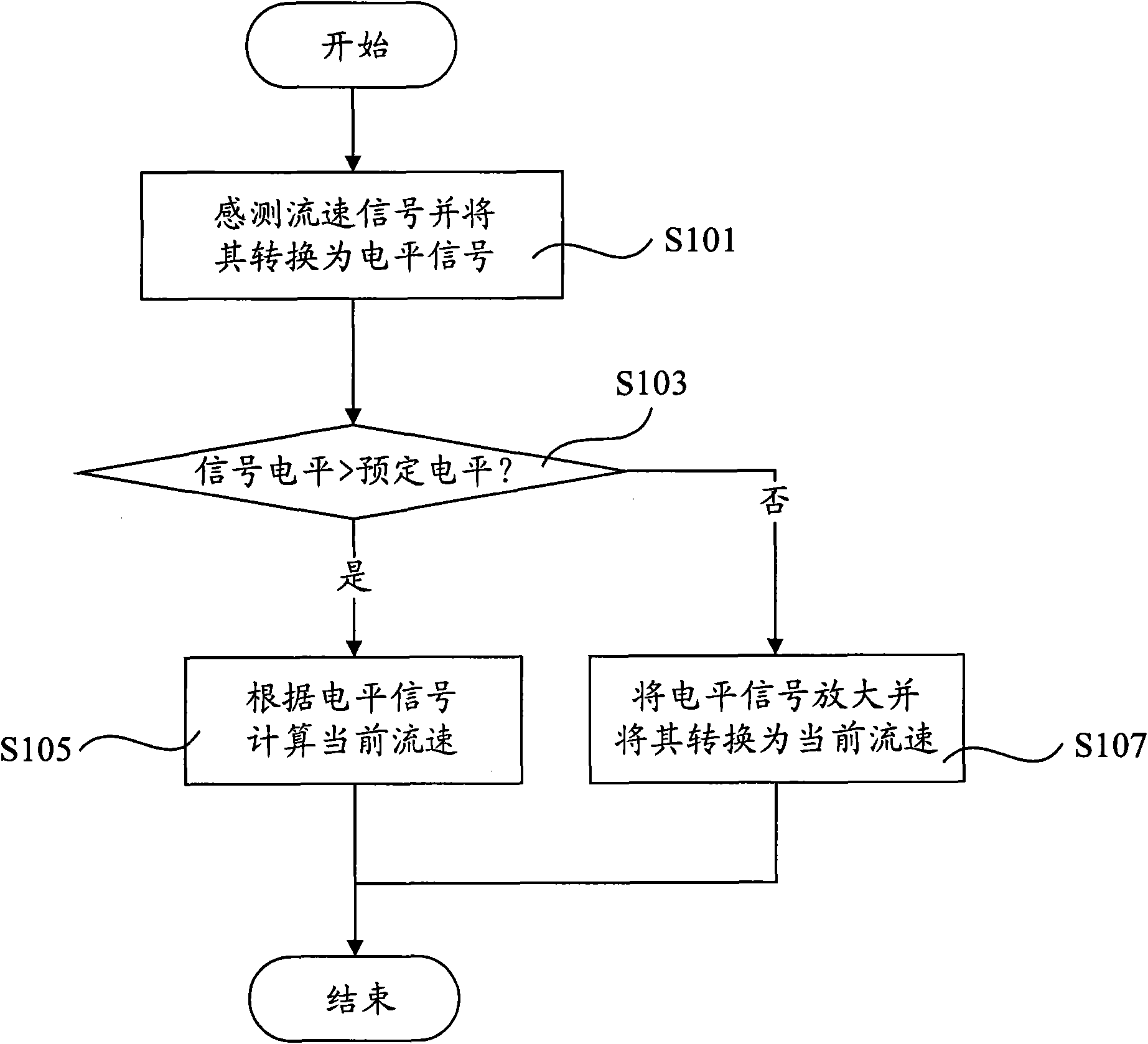
[0016] figure 1 is a flowchart of a method for measuring an inspiratory flow rate according to an embodiment of the present invention. Such as figure 1 As shown, the method includes the following steps:

[0017] Sensing the flow velocity signal and converting it into a level signal (S101);

[0018] Comparing the level signal with a predetermined level (S103); and

[0019] If the level signal is greater than the predetermined level, calculate the current flow rate according to the level signal (S105), and if the level signal is less than the predetermined level, amplify the level signal and calculate according to the amplified level signal current flow rate (S107);

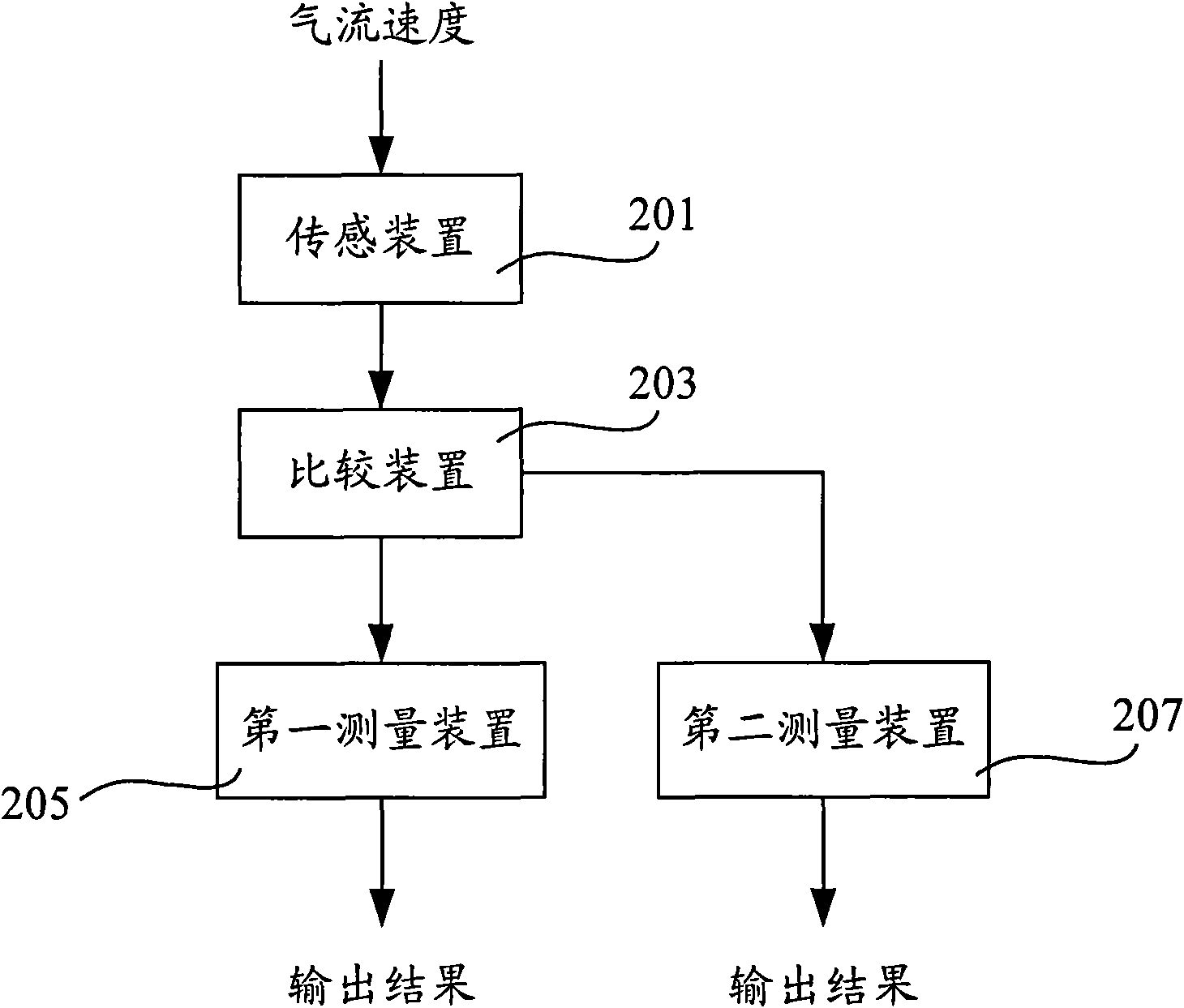
[0020] figure 2 is a block diagram of a system for measuring respiratory flow rate according to an embodiment of the present invention. Such as figure 2 As s...


PUM


Abstract

The invention discloses a method and a system for measuring aspiratory flow velocity by a differential pressure type sensor. The method comprises the following steps: sensing a flow velocity signal bya sensing device and converting the flow velocity signal into a level signal; comparing the level signal with a predetermined level by a comparer; sampling the level signal by a sampler under the condition that the level signal is more than the predetermined level so as to acquire an AD sampling signal, and calculating the current flow velocity by a first processor according to the AD sampling signal; amplifying the level signal by an amplification circuit under the condition that the level signal is less than the predetermined level; and sampling the amplified level signal by the sampler soas to acquire the amplified AD sampling signal, and calculating the current flow velocity by a second processor according the amplified AD sampling signal.

Description

technical field [0001] The present invention relates to a method and system for measuring inspiratory flow rate, more particularly, to a method and system for measuring inspiratory flow rate using a differential pressure sensor. Background technique [0002] In the ventilator, the gas flow rate needs to be measured, and the differential pressure flow sensor can be used to accurately measure the gas flow rate, and it is not affected by changes in airway pressure. However, when measuring at low flow rates, the output signal of the sensor is very weak and needs to be processed accordingly. [0003] The flow rate measurement in the ventilator mainly uses a hot wire or differential pressure flow sensor. Using a differential pressure sensor to measure the flow rate can directly obtain the volumetric flow rate. The measurement is more convenient, but the requirements for air resistance are relatively high. When the flow rate of the gas is low, the principle of the sensor determine...

Claims


Application Information

Patent Timeline
Patent Type & Authority Applications(China)
IPC IPC(8): G01P5/14
Inventor 金文贤王军李敬辉刘冬
Owner BEIJING AEONMED
Why Eureka
Try Eureka