Switching power supply with function of preventing overload and saturation of incremental current

A switching power supply and current overload technology, which is applied in the direction of output power conversion device, AC power input conversion to DC power output, electrical components, etc., can solve the problem of damage to transformers and power tubes, failure to deal with overload situations in time, and slow adjustment response speed and other problems to achieve the effect of preventing overload and saturation, solving the adjustment response speed too slow, and reducing the shutdown speed

Active Publication Date: 2011-07-27
SHAANXI REACTOR MICROELECTRONICS
View PDF0 Cites 0 Cited by
  • Summary
  • Abstract
  • Description
  • Claims
  • Application Information

AI Technical Summary

Problems solved by technology

The first method requires the power tube to have the ability to turn off quickly, otherwise the transformer and power tube will be damaged; while the second method has too many feedback links, it must first detect the overload, then adjust the error voltage, and then adjust The duty cycle, the adjustment response speed is too slow, and the overload situation cannot be handled in time, resulting in damage to the transformer and power tube

Method used


Image

  • Switching power supply with function of preventing overload and saturation of incremental current
  • Switching power supply with function of preventing overload and saturation of incremental current
  • Switching power supply with function of preventing overload and saturation of incremental current

Examples


Embodiment Construction

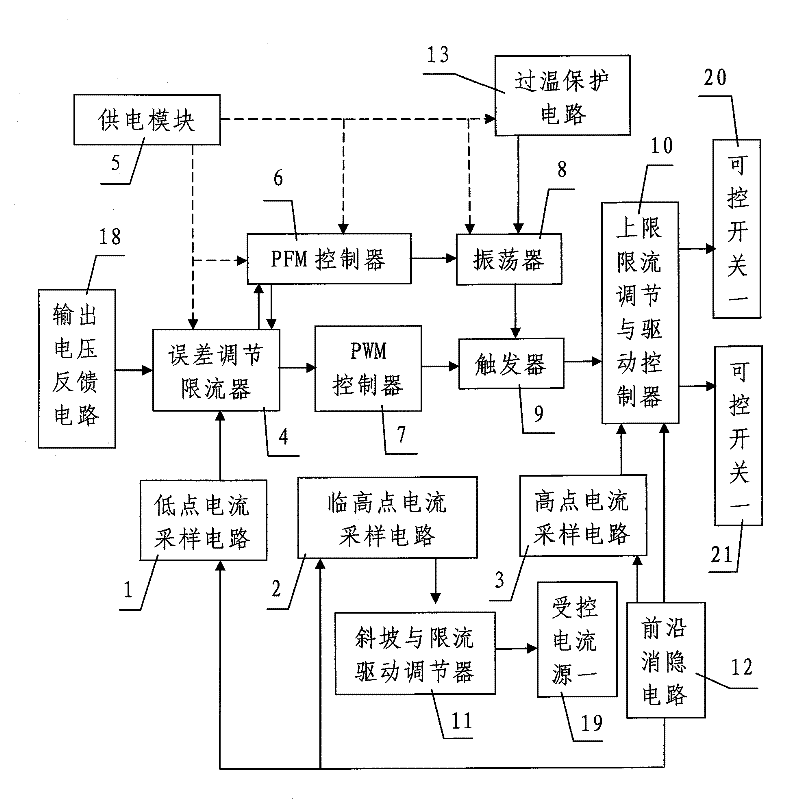
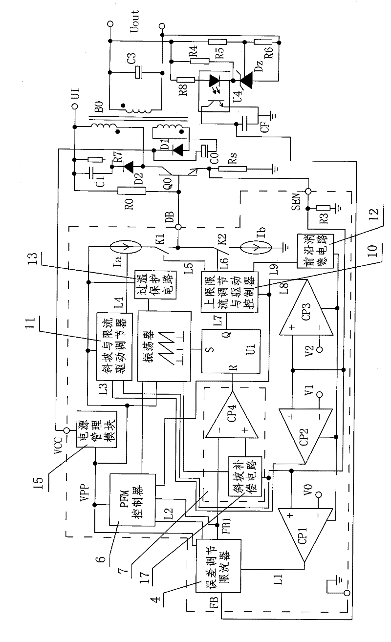
[0038] like figure 1 , figure 2 As shown, the present invention includes a power supply module 5 for supplying power to each electrical device, an output voltage feedback circuit 18 connected to the output terminal of the switching power supply, and performing cycle-by-cycle analysis of the instantaneous current value of the power transistor Q0 in the peripheral application circuit of the switching power supply, respectively. Sampled low point current sampling circuit 1, high point current sampling circuit 2 and high point current sampling circuit 3, controlled current source Ia (i.e. controlled Current source-19) and controllable switch K1 (i.e. controllable switch-20), the error adjustment current limiter 4 connected with the output end of the low-point current sampling circuit 1 and the output voltage feedback circuit 18 respectively, and the PFM controller 6 The oscillator 8 connected with the output terminal of the PWM controller 7, the PFM controller 6, the flip-flop 9...


PUM


Abstract

The invention discloses a switching power supply with the function of preventing overload and saturation of incremental current, comprising a power supply module, an output voltage feedback circuit, a low point current sampling circuit, a critical high point current sampling circuit, a high point current sampling circuit, a current source Ia, a switch K1, an error regulation current limiter, a PFM controller, a PWM controller, an oscillator, a trigger, an upper limit current limiting regulation and drive controller, an incline and current limiting drive regulator and a leading edge blanking circuit, wherein the low point current sampling circuit, the critical high point current sampling circuit and the high point current sampling circuit are used for sampling instantaneous current of a power tube, the current source Ia and the switch K1 are connected in a power supply loop of a base electrode of the power tube in series, the error regulation current limiter is respectively connected with the low point current sampling circuit and the output voltage feedback circuit, the trigger is respectively connected with the oscillator and the PWM controller, the upper limit current limiting regulation and drive controller is connected with the trigger and the high point current sampling circuit and controls the upper limit of the K1, and the incline and current limiting drive regulator isconnected with the critical high point current sampling circuit and controls the Ia. The invention has novel and reasonable circuit design, small loss and good use effect and can effectively overcomethe defects of higher requirement on the switching speed of the power tube and slower response regulation speed existing in the prior switching power supply.

Description

technical field [0001] The invention belongs to the technical field of switching power supply design, in particular to a switching power supply with progressive current overload and saturation prevention functions. Background technique [0002] Regarding switching power supplies, from the nature of input and output voltages, there are DC / DC (DC to DC) conversion power supplies or AC / DC (AC to DC) conversion power supplies; from the perspective of isolation, there are isolated and non-isolated conversion circuits. ; From the perspective of output voltage conversion, there are boost, buck and buck-boost conversion circuits; from the perspective of working mode, there are voltage mode and current mode; from the perspective of the current in the inductor, there are CCM (continuous current mode), BCM (critical current mode) and DCM (discontinuous current mode) switching power supply; from the perspective of control technology, there are PFM (pulse frequency control technology) an...

Claims


Application Information

Patent Timeline
Patent Type & Authority Patents(China)
IPC IPC(8): H02M7/217H02M1/32
Inventor 余远强
Owner SHAANXI REACTOR MICROELECTRONICS
Why Eureka
Try Eureka