
Automatic flow-regulating type water dropper

A dripper and automatic adjustment technology, applied in watering devices, gardening, botanical equipment and methods, etc., can solve the problems of adjusting the amount of dripping water, automatically changing the working state, etc., and achieve the effect of high energy saving advantages

Inactive Publication Date: 2011-04-06
XIAN UNIV OF TECH
View PDF0 Cites 0 Cited by
  • Summary
  • Abstract
  • Description
  • Claims
  • Application Information

AI Technical Summary

Problems solved by technology

[0003] The purpose of the present invention is to provide an automatic flow-adjusting dripper, which solves the problem that the existing dripper cannot automatically change the working state and adjust the dripping amount according to the actual demand of the soil moisture status during the irrigation process

Method used


Image

  • Automatic flow-regulating type water dropper
  • Automatic flow-regulating type water dropper
  • Automatic flow-regulating type water dropper

Examples


Embodiment Construction

[0015] The present invention will be described in detail below in conjunction with the accompanying drawings and specific embodiments.

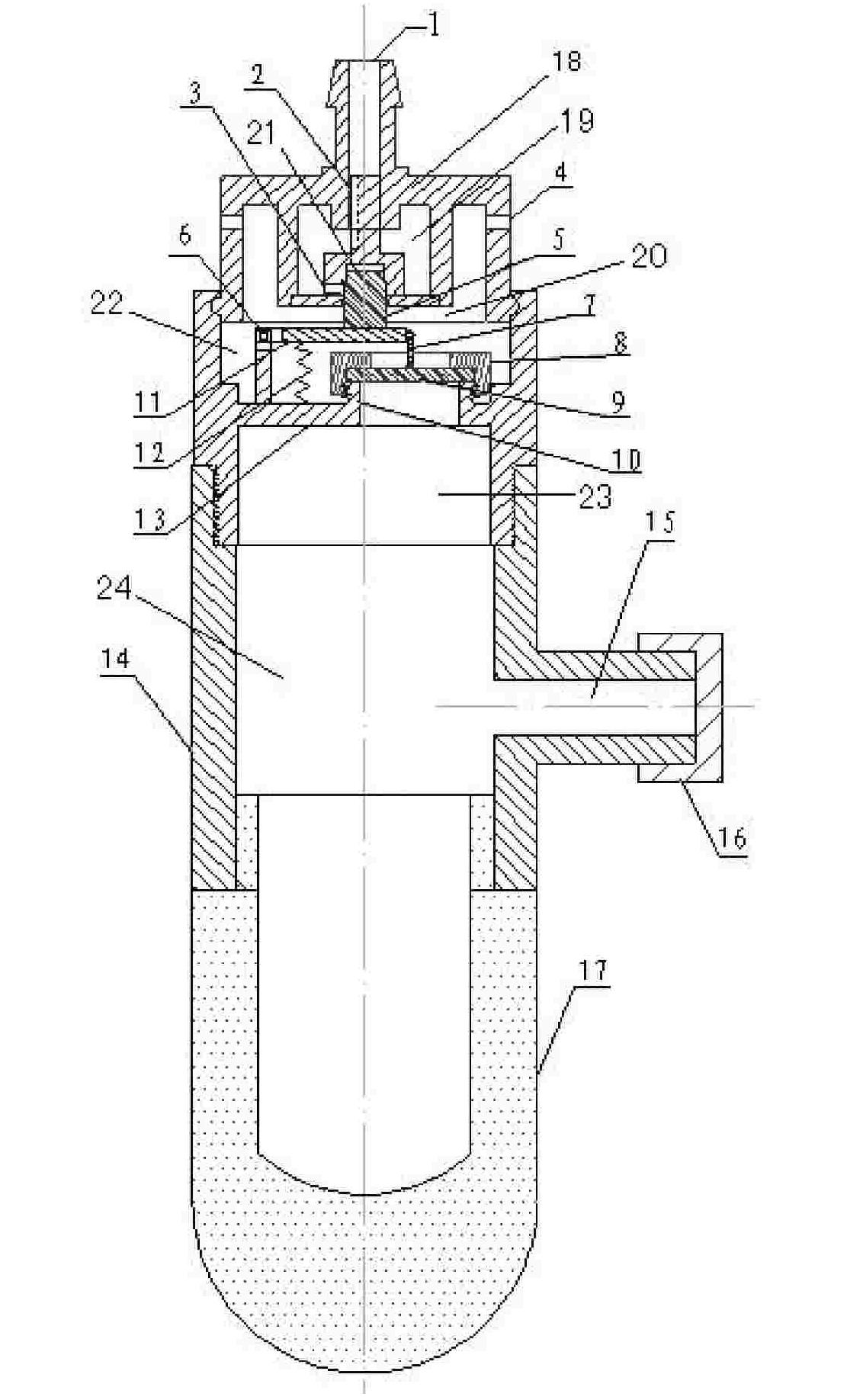
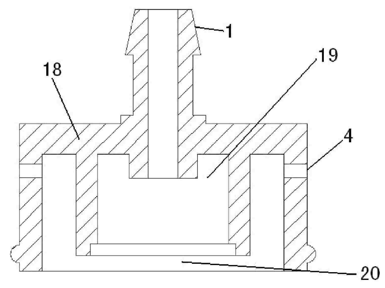
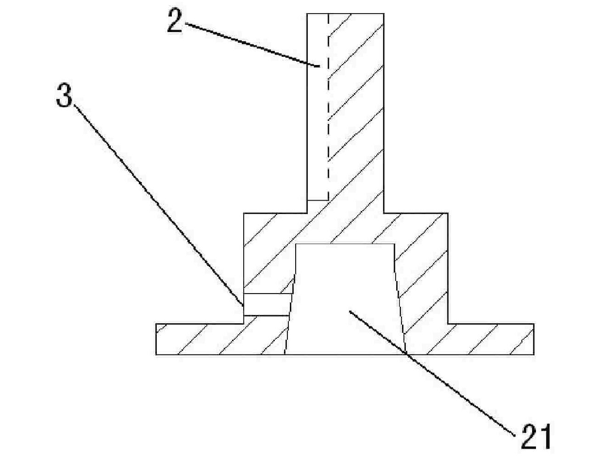
[0016] The structure of the automatic flow-adjusting dripper of the present invention is as follows: figure 1 As shown, it includes four parts: water inlet body, energy dissipation body, control body and negative pressure body. The structure of the influent body is as figure 2 As shown, it includes a base body 18 with cavities a19 and cavities b20 up and down inside. The top of the base body 18 is provided with a water inlet 1 communicating with the cavity a19, and both sides of the base body 18 are provided with water inlets 1 communicating with the cavity b20. Two water outlets4. The structure of the energy dissipator is as image 3 As shown, the bottom is a disk, and a cylinder is perpendicular to the center of the disk. The shapes of the disk and the cylinder match the cavity a19 inside the water inlet body. The side of the cylinder i...


PUM


Abstract

The invention discloses an automatic flow-regulating type water dropper comprising a water inlet body, an energy dissipation body, a control body and a negative pressure body, wherein the water inlet body comprises a base body, a cavity a and a cavity b are arranged in the base body vertically, the top of the base body is provided with a water inlet, the side surface of the base body is provided with a water outlet, the bottom of the energy dissipation body is provided with a disk, a column is perpendicular to the center of the disk, the side of the column is provided with a small overflowinghole, a cavity c is arranged in the column, and the top end of the column is provided with an energy dissipation channel; the control body comprises a baffle plate which is provided with a cavity d, a cavity e which is separated by a rubber diaphragm is arranged under the cavity d, the rubber diaphragm is connected with one end of a straight rod by a pull wire, the other end of the straight rod is fixed on the baffle plate, and the upper surface of the straight rod is provided with a rubber plug; the negative pressure body comprises an organic glass pipe, a cavity f is arranged in the organicglass pipe, one side of the organic glass pipe is provided with a water injection hole, and the lower end of the organic glass pipe is sleeved with an argil head. The automatic flow-regulating type water dropper has good water saving effect and high automation degree.

Description

technical field [0001] The invention belongs to the technical field of water-saving irrigation equipment, and in particular relates to an automatic flow-adjusting dripper. Background technique [0002] The dripper is the final water distribution equipment in the drip irrigation system. Its main function is to dissipate the energy of the pressurized water flow in the drip irrigation system, and to irrigate in the form of uniform dripping, so as to achieve the effect of saving water and increasing production. At present, the dripper products in the drip irrigation system have various structural types such as micro-tube type, orifice type, inlay type, patch type and plug-in type, and their functions are divided into flow compensation type and flow non-compensation type. Although the above drippers have different structures and functions, they have a common characteristic, that is, affected by factors such as the fixed structural design of the dripper and the size of the flow ch...

Claims


Application Information

Patent Timeline
Patent Type & Authority Patents(China)
IPC IPC(8): A01G25/02
Inventor 费良军冯俊杰黄修桥翟国亮邓忠赵红书
Owner XIAN UNIV OF TECH
Learn More