A multi-channel continuous pressure water supply type water heating equipment

A water heating and multi-channel technology, applied in lighting and heating equipment, water heaters, mechanical equipment, etc., can solve the problems of weak continuous water output, low power, low water pressure of water heating devices, etc., to shorten the heating time, The heating speed is fast and the effect of reducing the waste of heat

Inactive Publication Date: 2020-11-20
HENAN UNIV OF URBAN CONSTR
View PDF5 Cites 0 Cited by
  • Summary
  • Abstract
  • Description
  • Claims
  • Application Information

AI Technical Summary

Problems solved by technology

[0004] The purpose of the present invention is to provide a low-power multi-channel continuous steady-pressure water supply type water heating equipment for the problem of low water pressure and weak continuous water output ability of the water heating device

Method used


Image

  • A multi-channel continuous pressure water supply type water heating equipment
  • A multi-channel continuous pressure water supply type water heating equipment
  • A multi-channel continuous pressure water supply type water heating equipment

Examples


Embodiment 1

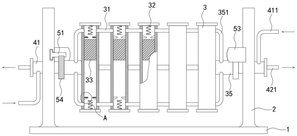
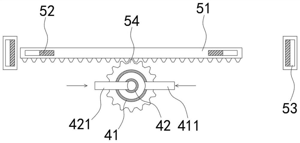
[0035] Such as Figure 1-3 As shown, a multi-channel continuous steady-pressure water supply type water heating equipment includes a base 1, and both sides of the upper end of the base 1 are fixedly connected with a fixing frame 2, and a circulation mechanism is installed on the fixing frame 2, between the two fixing frames 2 There are multiple sets of heating tubes 3 arranged side by side, and the adjacent heating tubes 3 are connected through a plurality of connecting tubes 31. The fixing frame 2 is provided with a driving mechanism for driving the heating tubes 3 to turn over. The heating tubes 3 are provided with:

[0036] Two heating wires 32 are fixedly installed at both ends of the heating tube 3 respectively;

[0037] Counterweight slider 33, counterweight slider 33 is arranged between two electric heating wires 32, and counterweight slider 33 is connected with the inner wall of heating tube 3 in a sliding seal, and counterweight slider 33 can adopt high temperature re...

Embodiment 2

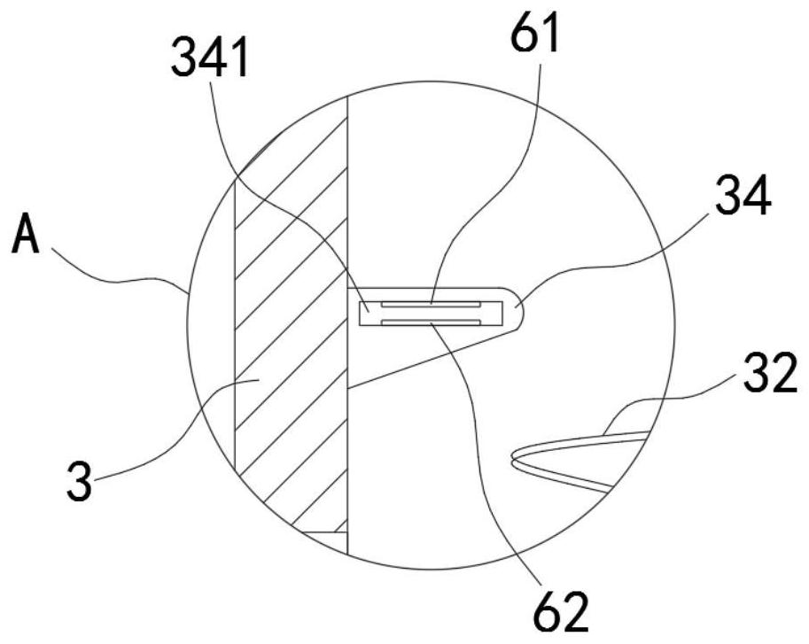
[0046] Such as Figure 4 As shown, the difference between this embodiment and Embodiment 1 is that the trigger switch includes an upper conductive sheet 71 arranged on the upper side wall of the cavity 341, and a lower conductive sheet 72 is arranged on the lower side wall of the cavity 341, and the lower conductive sheet 72 is arranged on the lower side wall of the cavity 341. The upper end of the sheet 72 is fixedly connected with a magnetic conductive sheet 74 via a spring 73 , and the counterweight slider 33 is embedded with a permanent magnet block that attracts opposite poles of the magnetic conductive sheet 74 .

[0047] In this embodiment, by embedding permanent magnets in the counterweight slider 33 , not only the trigger sensitivity to the trigger switch can be improved, but also the water body can be magnetized under the action of the permanent magnets to reduce the generation of scale.


PUM


Abstract

The invention belongs to the field of water heating equipment, and in particular relates to a multi-channel continuous water supply type water heating equipment, which includes a base, the two sides of the upper end of the base are fixedly connected with a fixed frame, and a circulation mechanism is installed on the fixed frame. There are multiple sets of heating tubes arranged side by side between the frames, and the adjacent heating tubes are connected through multiple connecting tubes. The fixed frame is provided with a driving mechanism for driving the heating tubes to turn over. There are two heating wires inside the heating tubes. , the two heating wires are respectively fixedly installed at both ends of the heating tube; the counterweight slider is set between the two heating wires, and the counterweight slider is in sliding and sealed connection with the inner wall of the heating tube; the limit protrusion The limit protrusion is arranged between the heating wire and the counterweight slider. The present invention can convert the gravity of the counterweight slider into the pressure on the hot water on the lower side by setting the counterweight slider, and can still maintain the stability of the water pressure when the water volume is small, so that the hot water can always be output stably .

Description

technical field [0001] The invention belongs to the field of water heating equipment, and in particular relates to a multi-channel continuous steady-pressure water supply type water heating equipment. Background technique [0002] The existing water heating device is usually a water storage type heating device, which has the following disadvantages: 1. Due to the large amount of water storage, the overall temperature rise of the water body is relatively slow. During the heating process, the waiting time is long, and continuous water discharge cannot be realized. Affect the user's use; 2. When the hot water is about to run out, due to the small amount of remaining water, there will often be a problem of low water pressure; 3. When the water storage type heating device is heated, it usually uses a high-power resistor to quickly heat the hot water. The heating is complete, and then it enters the heat preservation state. During the whole power consumption process, the power fluc...

Claims


Application Information

Patent Timeline
Patent Type & Authority Patents(China)
IPC IPC(8): F24H1/10F24H9/00F24H9/12F24H9/18F24H9/20C02F5/00
CPCF24H1/102F24H9/0015F24H9/1818F24H9/2028C02F5/00C02F2303/22F24H9/139
Inventor 黄战峰张洛花林逢煌陈鑫洋曹智伟丁绍鹏陈长松
Owner HENAN UNIV OF URBAN CONSTR
Why Eureka
Try Eureka