
Ball taking and casting device, paraffin removal ball casting machine for oil transmission pipeline and ball casting method

A technology of wax removal and ball-throwing device for oil pipelines, which is applied in cleaning methods and appliances, chemical instruments and methods, and cleaning hollow objects, etc. It can solve the problems of oil pipeline blockage, cumbersome operation, lame pressure, etc., and achieve the effect of structural realization

Active Publication Date: 2010-02-17
北京众博达石油科技有限公司 +1
View PDF1 Cites 12 Cited by
  • Summary
  • Abstract
  • Description
  • Claims
  • Application Information

AI Technical Summary

Problems solved by technology

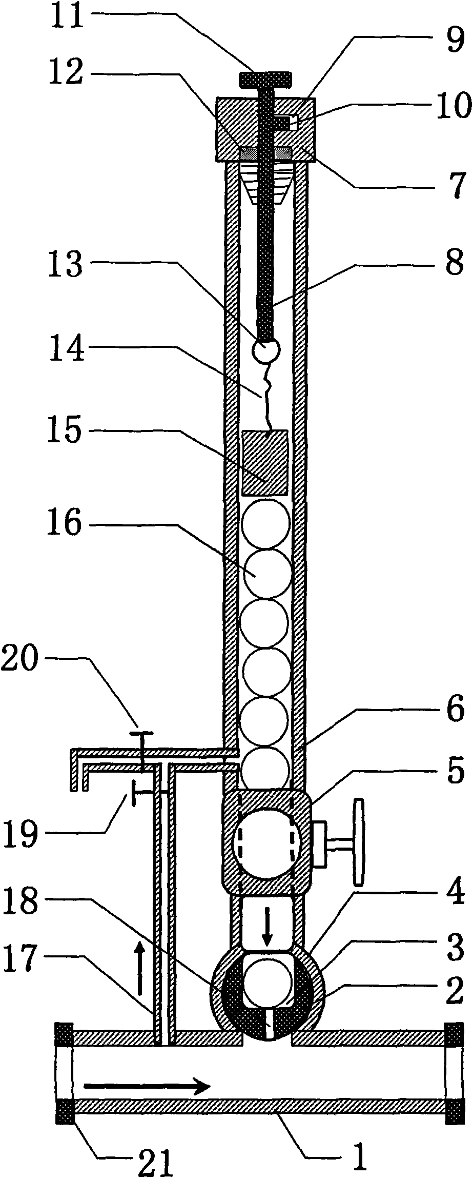
[0004] The present invention aims at the cumbersome operation of manual ball throwing in the prior art, and a bypass must be established, while the existing wax removal ball throwing device is easy to block the oil pipeline and often produces lame pressure, and provides a new type of ball taking and throwing device and adopts The oil pipeline wax removal machine for taking and throwing the ball can realize the ball throwing under pressure, and it will not be under pressure when working, and does not depend on other valves and bypasses, which can simplify the operation procedure and reduce labor intensity, and has a simple structure and is easy to operate. advantages, the present invention also relates to a method for removing wax from oil pipelines and throwing balls

Method used


Image

  • Ball taking and casting device, paraffin removal ball casting machine for oil transmission pipeline and ball casting method
  • Ball taking and casting device, paraffin removal ball casting machine for oil transmission pipeline and ball casting method
  • Ball taking and casting device, paraffin removal ball casting machine for oil transmission pipeline and ball casting method

Examples


Embodiment Construction

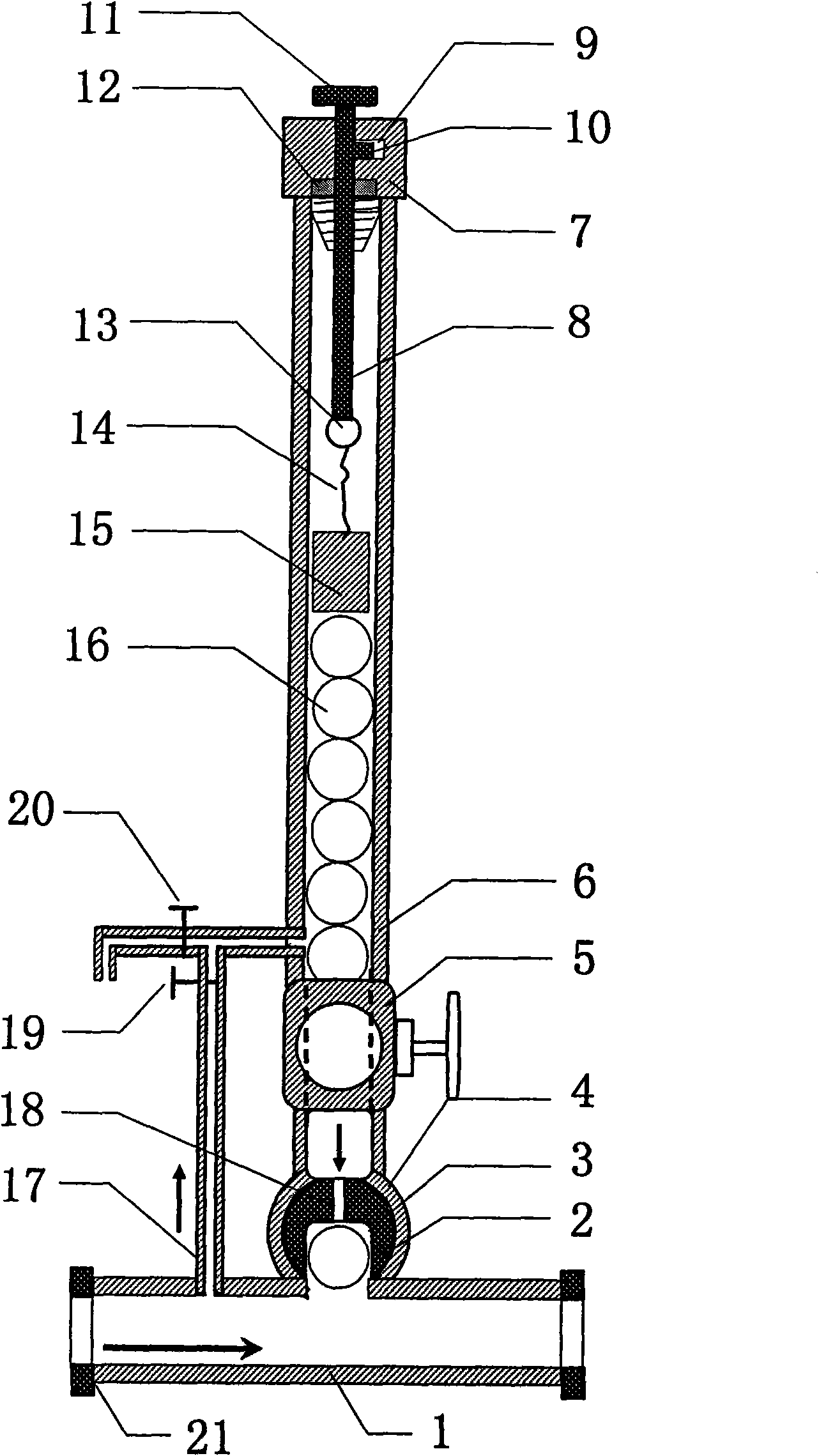
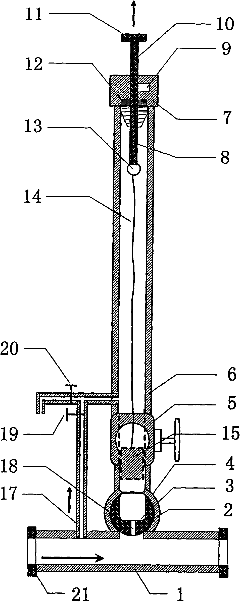
[0037] The present invention will be described below in conjunction with the accompanying drawings. figure 1 It is a structural schematic diagram of a preferred embodiment of the oil pipeline wax removal and ball throwing machine of the present invention. The oil pipeline wax removal ball throwing machine includes pressure balance pipes 17 arranged in sequence along the oil delivery direction and communicated with the oil delivery pipeline 1 respectively and a ball taking and throwing device The ball-taking device comprises a ball storage tube 6, a ball-storage rotor shell 4 and a ball-storage rotor 2 that rotates in the ball-storage rotor shell 4. The top of the ball-storage tube 6 is sealed by a plug 7, and the bottom of the ball-storage tube 6 is sealed. It is fixedly connected and communicated with the upper end of the ball-taking rotor housing 4, and the lower end of the ball-taking rotor housing 4 is fixedly connected and communicated with the oil pipeline 1. Diameter, s...


PUM


Abstract

The invention relates to a ball taking and casting device, a paraffin removal ball casting machine for an oil transmission pipeline and a ball casting method. The ball taking and casting device is communicated with the oil transmission pipeline and comprises a ball storage barrel, a ball taking and casting rotor shell and a ball taking and casting rotor which rotates in the ball taking and castingrotor shell, wherein the top end of the ball storage barrel is sealed and the bottom end is fixedly connected and communicated with the upper end of the ball taking and casting rotor shell; the ballstorage barrel has a pushing force structure for pushing a paraffin removal ball to the bottom end; the lower end of the ball taking and casting rotor shell is fixedly connected and communicated withthe oil transmission pipeline; the ball taking and casting rotor comprises a rotor main body, a ball taking and casting chamber, a pressure balance hole and a rotor rotating shaft; the ball taking andcasting chamber has a space for containing the paraffin removal ball, the diameter of a space opening is slightly larger than that of the paraffin removal ball, and the pressure balance hole penetrates through the rotor main body from the back of the ball taking and casting chamber and is communicated with the ball taking and casting chamber. The ball taking and casting device automatically caststhe ball with pressure without pressuring out or depending on other valves and bypasses and has the advantages of simple structure and easy operation.

Description

technical field [0001] The invention relates to a technique for throwing wax-removing balls during crude oil transportation in oil pipelines, in particular to a ball taking and throwing device capable of automatically throwing balls under pressure at regular intervals, an oil pipeline wax-removing ball throwing machine and a ball throwing method using the ball taking and throwing device. Background technique [0002] The extracted underground crude oil contains a large amount of paraffin. During the normal temperature oil transportation process at the wellhead or well site of some oilfields in my country, due to the large difference between the temperature of the crude oil and the surface temperature, the crude oil will precipitate paraffin and adhere to the inner wall of the oil pipeline. After a period of Over time, the precipitated paraffin will greatly reduce the crude oil transportation capacity of the oil pipeline, and even block the oil pipeline, affecting the oil flow ...

Claims


Application Information

Patent Timeline
IPC IPC(8): B08B13/00B08B9/04
Inventor 刘广峰顾岱鸿田树宝丑世龙王建军康乐王永全魏明蒲新阳仲庭祥
Owner 北京众博达石油科技有限公司
Learn More