Boot shape maintaining body

A technology for maintaining body and boots, which is applied to boot legs, uppers, clothing, etc., and can solve problems such as moisture cannot be released

Inactive Publication Date: 2010-02-17
INED BUSINESS FASHION PLANNING
View PDF2 Cites 0 Cited by
  • Summary
  • Abstract
  • Description
  • Claims
  • Application Information

AI Technical Summary

Problems solved by technology

[0006] As a result, the moisture in the inner bottom of the boot cannot escape, which becomes a cause for bacteria to multiply and give off a bad smell

Method used


Image

  • Boot shape maintaining body
  • Boot shape maintaining body
  • Boot shape maintaining body

Examples


no. 1 approach

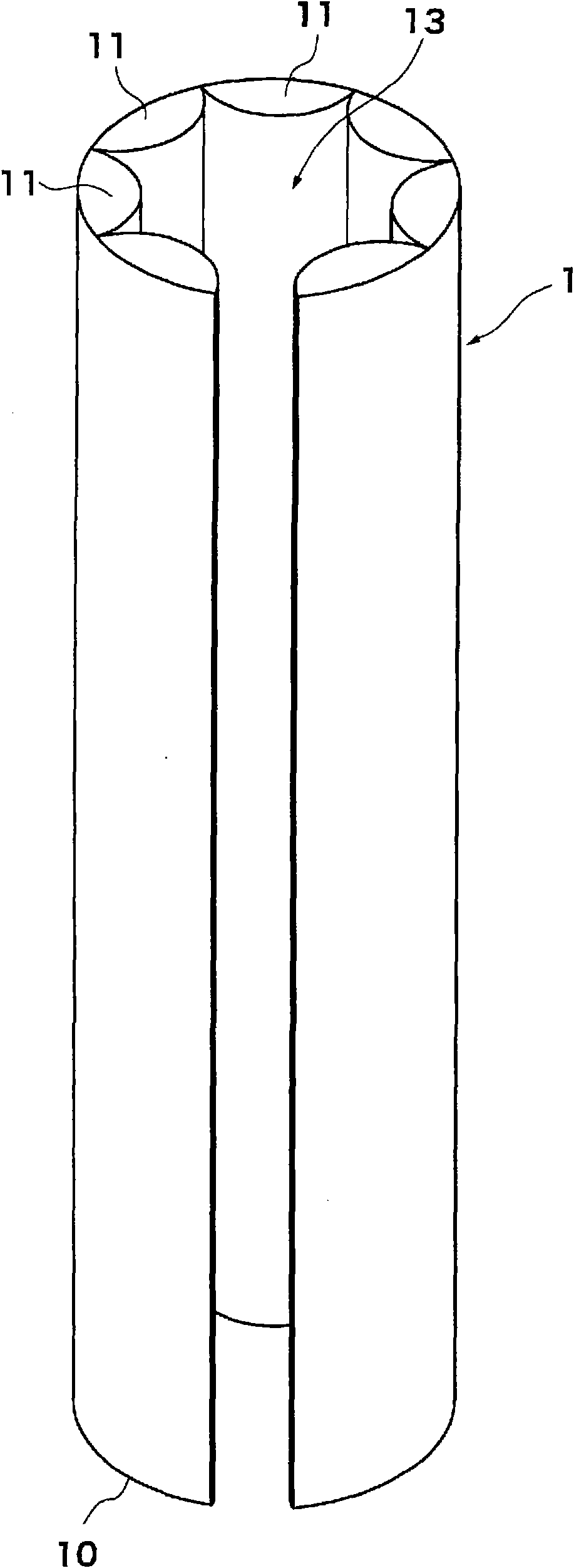
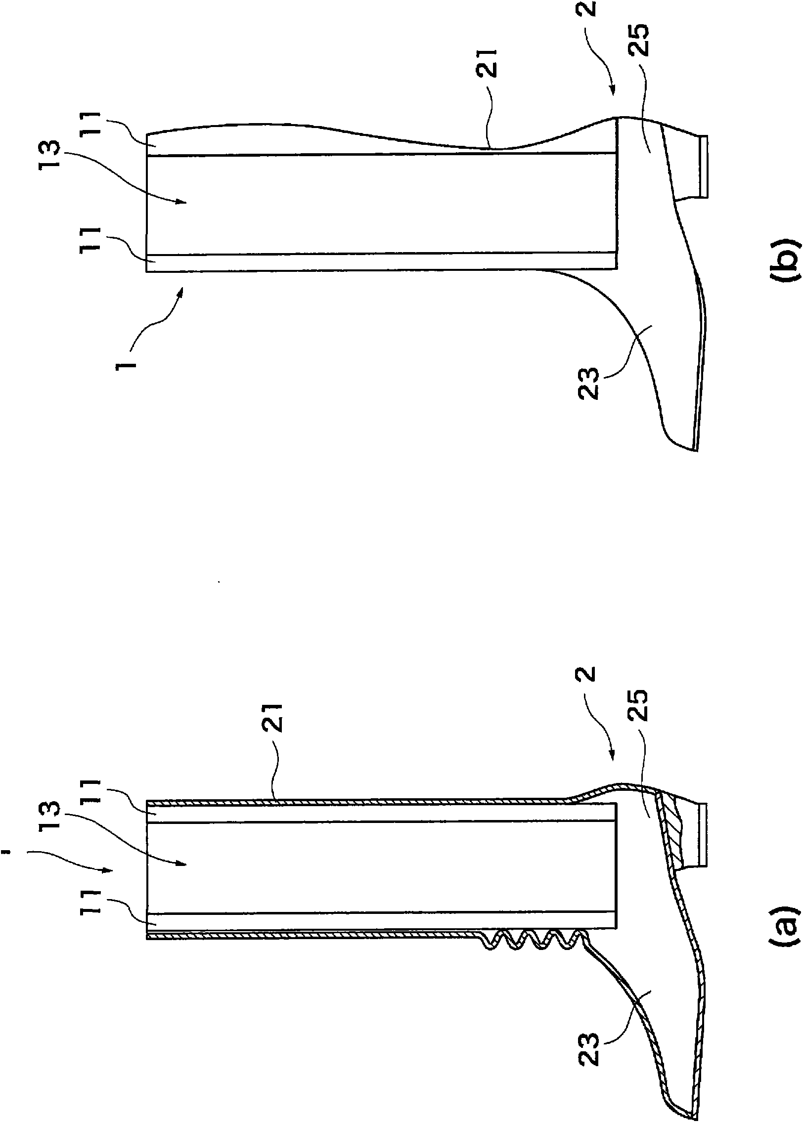
[0026] figure 1 It is a perspective view of the boot shape retainer 1 as the first embodiment to which the present invention is applied. The boot shape retainer 1 is mainly constituted by rolling and connecting a plastic film 10 in a cylindrical shape.

[0027] The plastic film 10 is a thermoplastic resin film such as polyethylene that does not have air permeability. That is, the thermoplastic resin can be appropriately selected from polypropylene, polyethylene terephthalate, nylon, polyvinyl chloride, polycarbonate, and the like in addition to polyethylene.

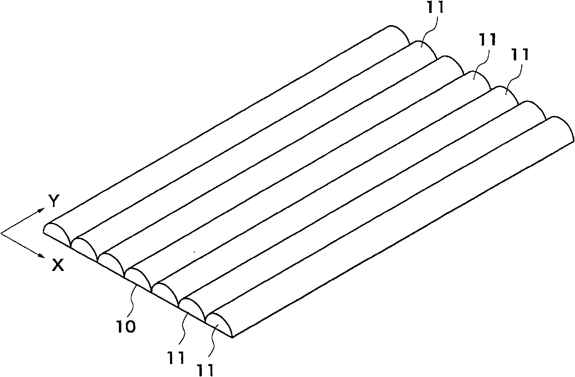
[0028] Such as figure 2 As shown, in the plastic film 10 , the air cells 11 are arranged in a row along the width direction x. The air cells 11 are preliminarily sealed with gas and are formed in a long and thin shape in the vertical direction y. The air chamber 11 is constituted by forming the plastic film 10 by two rectangular film sheets, and after overlapping the two film sheets, performing thermocompression bond...

no. 2 approach

[0039] Figure 5 (a) is a perspective view showing a boot shape retainer 3 as a second embodiment to which the present invention is applied. The boot shape retainer 3 has a cylindrical main body 30 formed of a plastic film preliminarily sealed with gas, and at least one protrusion 32 protruding further downward from the lower end of the main body 30 . A through hole 31 is provided in the cylindrical body portion 30 . In addition, in the following description, the case where two protrusion parts 32 are formed is demonstrated as an example, However, It is not limited to this, You may comprise in any number, volume, and shape.

[0040] The plastic film is a thermoplastic resin film such as polyethylene that does not have air permeability. That is, the thermoplastic resin can be appropriately selected from polypropylene, polyethylene terephthalate, nylon, polyvinyl chloride, polycarbonate, and the like in addition to polyethylene.

[0041] The main body portion 30 can maintain ...

no. 3 approach

[0053] Figure 8 (a) and (b) are perspective views showing a boot shape retainer 4 as a third embodiment to which the present invention is applied. The boot shape retainer 4 has a cylindrical main body 40 formed of a plastic film pre-enclosed with gas, and a through-hole 42b provided in the lower part of the side wall surface of the main body 40 or a hole formed in the lower end of the side wall of the main body 40. Groove portion 42a. In addition, the groove portion 42a or the through-hole 42b may be formed in any shape, and may be formed in any number. The through hole 42b is connected to the through hole 41 formed in the cylindrical body part 40 . The position where the through hole 42b is provided is pre-adjusted at least in relation to the position of the inner bottom 23 of the boot 2, but it is preferably formed at least at an arbitrary position of the lower half. The main body portion 40 can maintain its shape by enclosing air.

[0054] When actually using the boot ...


PUM


Abstract

A boot shape maintaining body maintains a boot in a specific shape and can open an inner bottom section of the boot to outside air while maintaining the shape, removing bad odor from the inner bottom section. The boot shape maintaining body (1) is inserted into a trunk tube section (21) of a boot (3) and maintains the shape of the trunk tube section (21). The boot shape maintaining body (1) has abody section (30) constructed by forming a plastic sheet (10), in which gas is previously sealed, into a circular tube shape, and further has a through hole (42b) provided in the lower part of a sidewall surface of the body section (30) or, alternatively, has a groove section (42a) formed in the lower end of the body section (30). The body section (30) has a constant shape formed by gas.

Description

technical field [0001] The present invention relates to a boot shape retaining body for retaining a boot in a certain shape. Background technique [0002] When the boots and the like are taken off and placed in a hallway or the like, the shaft portion of the boots is likely to bend. If left in such a state for a long time, wrinkles or even deformation may occur at the bent part of the boot shaft. For this reason, when the boots are not used for a long time, they need to be stored in such a way that the boot shaft does not bend. [0003] Conventionally, a bootskeeper (bootskeeper) has been proposed in order to prevent such bending of the boot shaft portion of the boot (for example, refer to Patent Document 1). The bootie is inserted into a shaft of a boot, maintains the shape of the shaft, and has a pleat flattening member for flattening a pleat in the vicinity of an ankle joint of the shaft. In addition, in the technology disclosed in Patent Document 2, a shape retainer m...

Claims


Application Information

Patent Timeline
Patent Type & Authority Applications(China)
IPC IPC(8): A43D3/14
CPCA43D3/1416A43B23/02
Inventor 栗田贵史深津敦
Owner INED BUSINESS FASHION PLANNING
Why Eureka
Try Eureka