Information recording medium, recording method, recording device, and integrated circuit

A technology for information recording and recording devices, which is applied in the field of information recording media, recording, recording devices and integrated circuits, can solve the problem that the recording film characteristics of the outermost periphery cannot be guaranteed, the recording conditions of the outer peripheral region cannot be optimally obtained, and the Recording conditions and other issues, to achieve the effect of good recording quality, accurate recording, high-speed recording and recording quality

Inactive Publication Date: 2010-02-17
PANASONIC CORP
View PDF1 Cites 0 Cited by
  • Summary
  • Abstract
  • Description
  • Claims
  • Application Information

AI Technical Summary

Problems solved by technology

As mentioned above, since the maximum recording speed at the innermost peripheral position is 5X, it is not possible to obtain a recording condition higher than 6X in the power calibration area where the film characteristics are guaranteed.
There may be a power calibration area on the outermost circumference, but sometimes the recording film characteristics of the outermost circumference cannot be guaranteed, and the recording conditions of ×6 cannot be obtained optimally.
Therefore, when it is considered that the Z-CLV is used to record at a CLV of 5X speed or lower in the area on the inner peripheral side and at a CLV of 6X or higher in the outer peripheral side area, it is not possible to optimally determine the Recording Conditions for Areas

Method used


Image

  • Information recording medium, recording method, recording device, and integrated circuit
  • Information recording medium, recording method, recording device, and integrated circuit
  • Information recording medium, recording method, recording device, and integrated circuit

Examples


no. 1 Embodiment approach

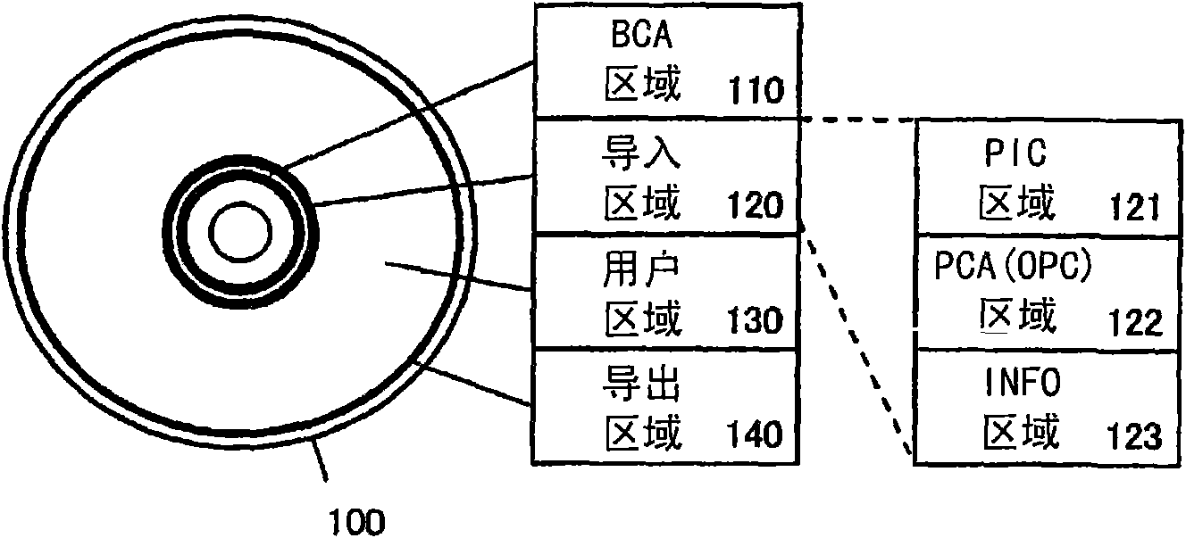
[0090] The first embodiment of the present invention will be described below. First, in reference to figure 1 The track structure of the optical disc 100 of this embodiment will be described together with the following. The optical disc 100 includes a recording layer. The recording layer records data onto the optical disc 100 by forming recording marks and spaces between the recording marks and the recording marks. Disc 100 as referenced Figure 16 As explained, concentric orbits are formed.

[0091] The optical disc 100 includes a BCA (Burst Cutting Area: Burst Cutting Area) area 110 , a lead-in area 120 , a user area 130 and a lead-out area 140 .

[0092] The BCA area 110 is pre-recorded with a barcode-like signal. This signal includes a unique number for identifying the medium of each optical disc, copyright information, and disc characteristic information. The disc characteristic information includes identification information of recording layer number and address m...

no. 2 Embodiment approach

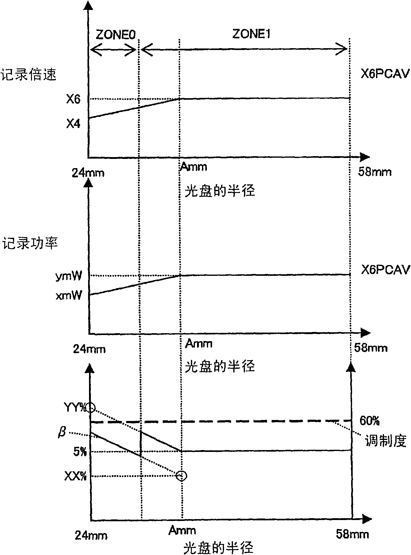
[0129] A second embodiment of the present invention will be described below. image 3 An example of a recording speed and recording power control method according to the second embodiment of the present invention, that is, a recording speed and recording power control method for recording at 6x speed in a BD is shown. The optical disc of this embodiment is suitable for recording at, for example, 4x speed (×4), 6x speed (×6) and 8x speed (×8). A method of controlling the recording speed and recording power by ×6 CAV using this optical disc is shown. image 3 , the horizontal axis of the three graphs represents the radial position [mm] in the range from the inner circumference (24 mm) to the outer circumference (58 mm) of the optical disc. In the figure, the vertical axis of the upper graph represents the recording speed, the vertical axis of the central graph represents the recording power, and the vertical axis of the lower graph represents β and modulation degree.

[0130] ...

no. 3 Embodiment approach

[0180] Next, an optical disc device that performs optimal recording power control using each recording condition at each recording speed will be described.

[0181] Figure 6 It is a block diagram showing the configuration of an embodiment of an optical disc device as a recording device of the present invention. exist Figure 6 Among them, the optical disc device has an optical head 131, a motor 132, a servo circuit 133, a track address reproducing circuit 134, a CPU 135, a data recording and reproducing circuit 136, and a laser drive circuit 137, and records information on the optical disc 100.

[0182] Disc 100 as referenced Figure 16 As explained, there are tracks for recording data, and address values ​​are recorded in accordance with the address format on the track. The track is formed in a snaking manner, and address values ​​are recorded according to the frequency or phase modulation of the snaking. and, with reference to figure 1 With the track structure describ...


PUM

PropertyMeasurementUnit
thicknessaaaaaaaaaa

Abstract

Provided is an information recording medium which is compatible with a plurality of recording speeds and contains recording conditions of the recording speeds which have been recorded in advance. The recording conditions include: a parameter concerning a recording power for recording at each of the recording speeds and a parameter concerning a recording waveform; and other parameters concerning arecording power for performing a recording at a recording speed other than the aforementioned recording speeds by using a parameter concerning a recording waveform for performing a recording at the recording speed.

Description

technical field [0001] The present invention relates to an information recording medium, a recording method for recording information on the information recording medium, a recording device for recording information on the information recording medium and an integrated circuit for the recording device, in particular to a method for determining recording The method used to record power. Background technique [0002] Recording types such as record-once information recording media (CD-R, DVD-R, BD-R) and rewritable information recording media (CD-RW, DVD-RW, BD-RE) that use lasers to record information are currently widely used. Information recording medium. Such an information recording medium that uses laser light to record information is generally called an optical disc. Hereinafter, the information recording medium is simply called an optical disk in this specification. [0003] In an optical disc device that records information on such a recordable optical disc using la...

Claims


Application Information

Patent Timeline
Patent Type & Authority Applications(China)
IPC IPC(8): G11B7/0045G11B7/125G11B7/007
CPCG11B7/1267G11B7/0062G11B7/00736G11B7/007G11B7/0045G11B7/1263
Inventor 宫下晴旬日野泰守中村敦史东海林卫大西完司
Owner PANASONIC CORP
Why Eureka
Try Eureka