LED ground display device
A display device and ground technology, applied to identification devices, static indicators, instruments, etc., can solve the problems of many connections, many display components, poor selectivity, etc.
- Summary
- Abstract
- Description
- Claims
- Application Information
AI Technical Summary
Problems solved by technology
Method used
Image
Examples
Embodiment 1
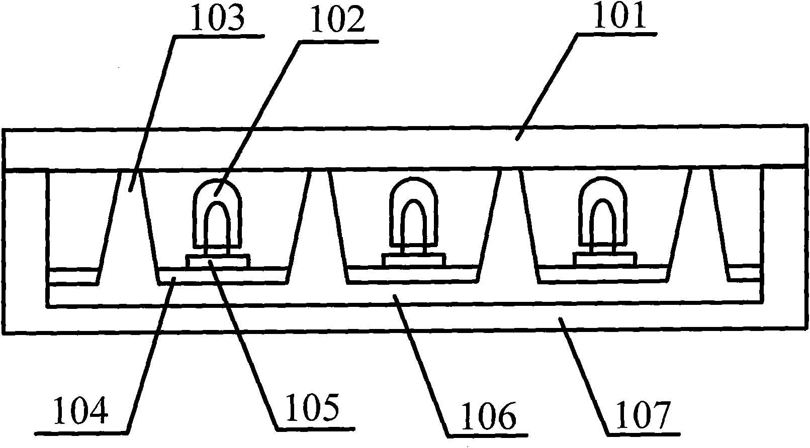
[0023] Such as figure 1 As shown, this embodiment provides an LED floor display device, the LED floor display device is formed by assembling one LED floor display module or a plurality of LED floor display modules, and the LED floor display device is generally installed on the ground It can be used to display graphics, text, letters, pictures, etc., or to display flickering, chasing and other effects, for example, it can be used in large public places or stage display screens.
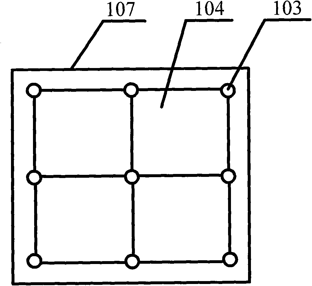
[0024] Wherein, each LED floor display module includes a housing 107 , a panel 101 , a support plate 106 and one or more installation plates 104 .
[0025] The housing 107 can be made of plastic material, metal material, etc., and the housing 107 is fixedly connected to the panel 101, for example, by bonding, clamping, plugging, shafting, etc., so that the The housing 107 is fixedly connected to the panel 101 . Moreover, it forms a box body with sealed edges and a cavity with the panel 101 . The pan...
Embodiment 2
[0042] Such as figure 2 As shown, on the basis of the above examples, the support plate is set as a metal support plate. The metal support plate has good rigidity and can play a very good load-bearing role, and the metal support plate also has a good The heat dissipation effect enables the heat in the LED floor display device to be quickly dissipated through the metal support plate, and is exported to the outside through the housing 107 or the heat dissipation device provided. The heat dissipation device may be a heat dissipation hole , heat sink, heat sink, fan, etc.
[0043] In addition, the protruding portions 103 provided on the supporting plate are balanced in mass relative to the supporting plate, so that the supporting plate provided with each protruding portion 103 can maintain a balanced mass as a whole, and it is not easy to balance the quality of the local parts. When the support plate supports the panel, it can be stressed evenly and can withstand greater pressur...
Embodiment 3
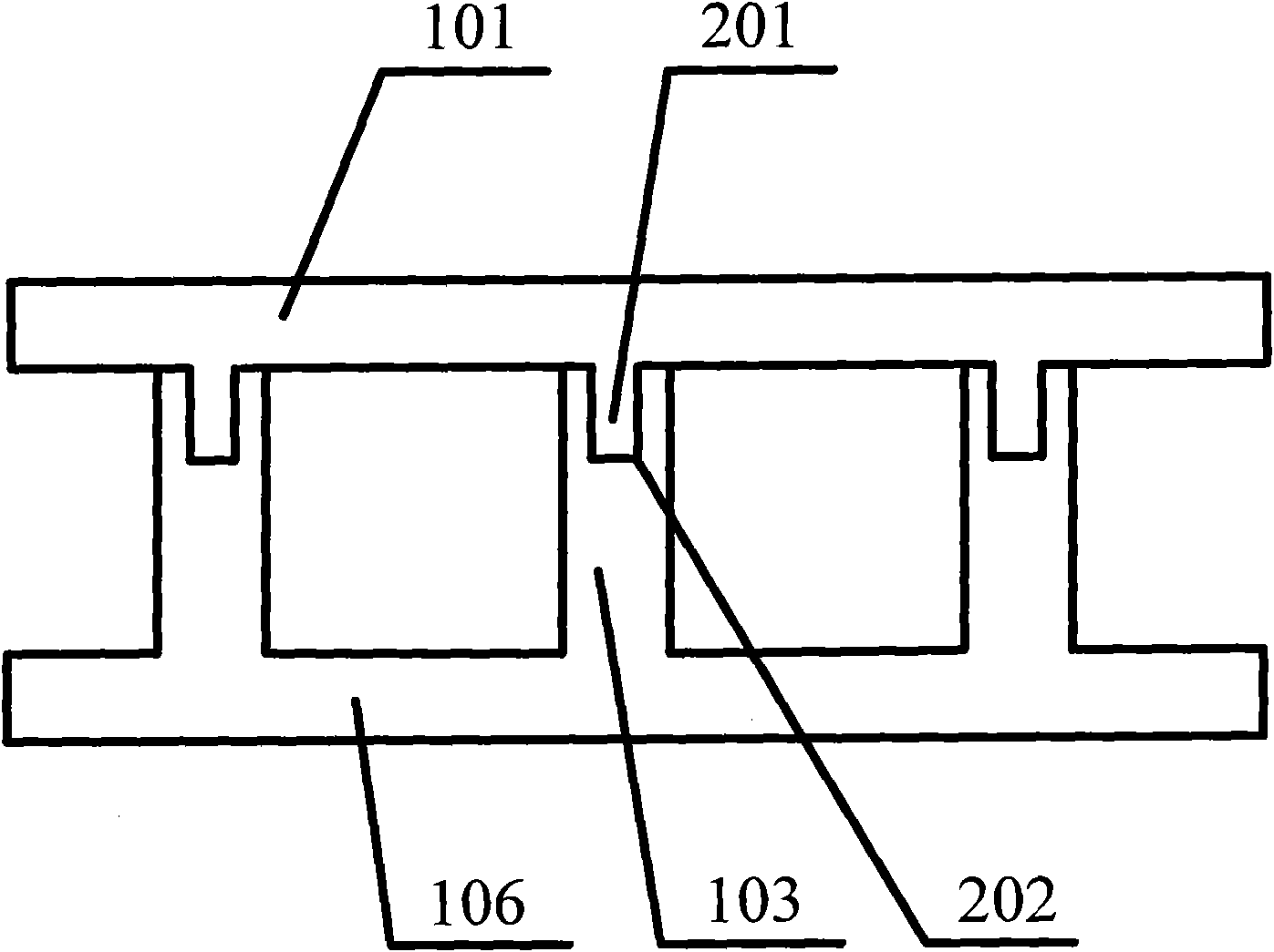
[0047] Such as image 3 As shown, on the basis of the above examples, in the support plate 106, any raised portion 103 is also provided with a fixing position 202, and the panel 101 is provided with a matching fixing portion 201, and the fixing portion 201 is adapted and fixedly connected with the fixing position 202, so that the panel 101 and the support plate 106 are more fixedly connected, and the displacement is not easy to occur, so that the LED floor display device is more stable and safe in use.
[0048] For example, the fixing position 202 is set as a groove, and the fixing portion 201 is set as a matching raised strip, that is, the shape and size of the groove and the raised strip are consistent, for example, the If the shape is square, then the shape of the raised strip is also square, and the length of the raised strip is equal to the groove depth of the groove, and at the same time, the size of the raised strip is consistent with the size of the groove, so that the...
PUM
 Abstract
Description
Claims
Application Information
 - R&D
- Intellectual Property
- Life Sciences
- Materials
- Tech Scout
- Unparalleled Data Quality
- Higher Quality Content
- 60% Fewer Hallucinations
Browse by: Latest US Patents, China's latest patents, Technical Efficacy Thesaurus, Application Domain, Technology Topic, Popular Technical Reports.
© 2025 PatSnap. All rights reserved.Legal|Privacy policy|Modern Slavery Act Transparency Statement|Sitemap|About US| Contact US: help@patsnap.com


