
Wind-driven electricity generation device with savonius rotor

一种设备、转子的技术,应用在发电机和分段式转子领域,达到装配简单的效果

Inactive Publication Date: 2010-02-24
SAUER ENERGY
View PDF0 Cites 13 Cited by
  • Summary
  • Abstract
  • Description
  • Claims
  • Application Information

AI Technical Summary

Problems solved by technology

Although these attempts can prevent or reduce the extent of damage to such blades, repair or replacement of damaged blades will also require the use of basic dismantling and repairing devices and facilities

Method used


Image

  • Wind-driven electricity generation device with savonius rotor
  • Wind-driven electricity generation device with savonius rotor
  • Wind-driven electricity generation device with savonius rotor

Examples


Embodiment Construction

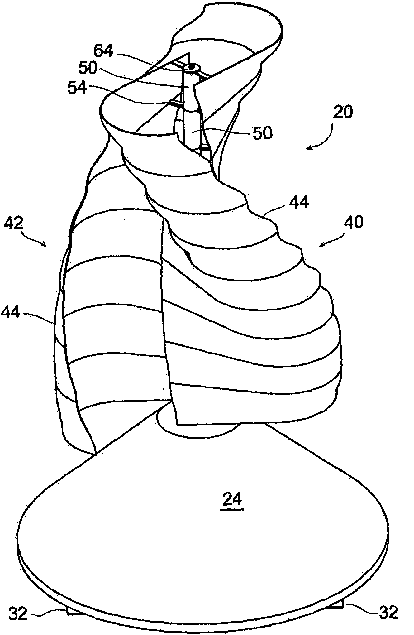
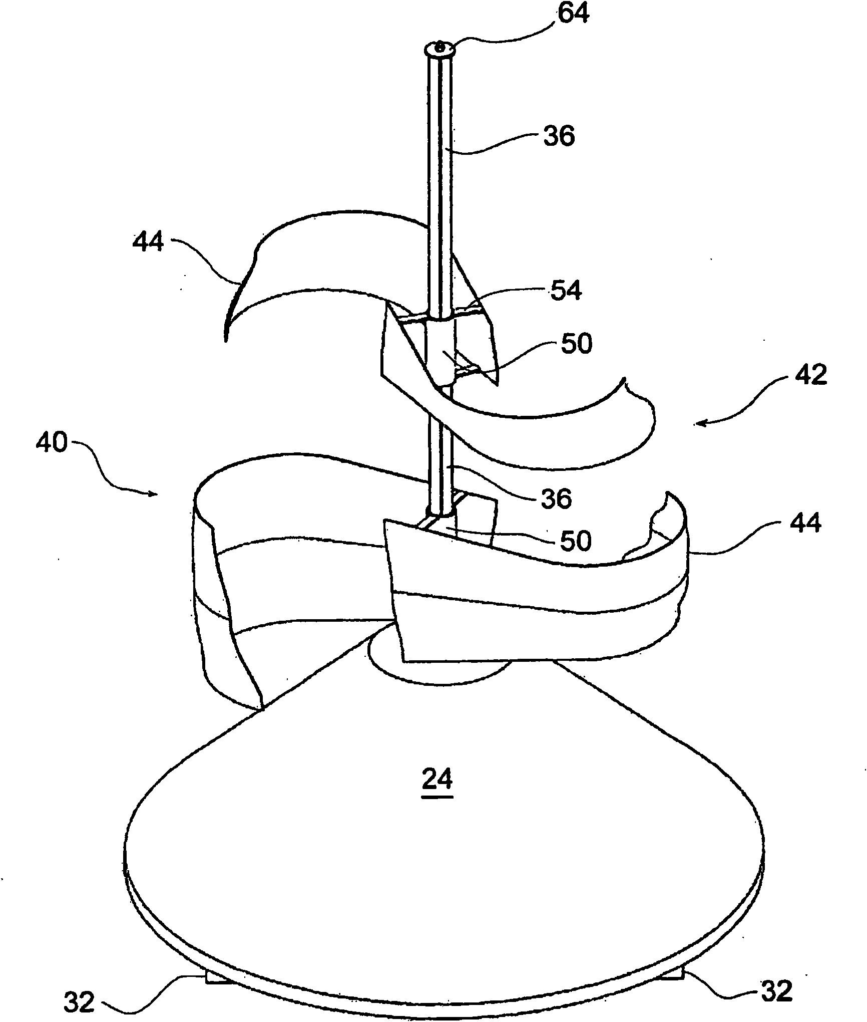
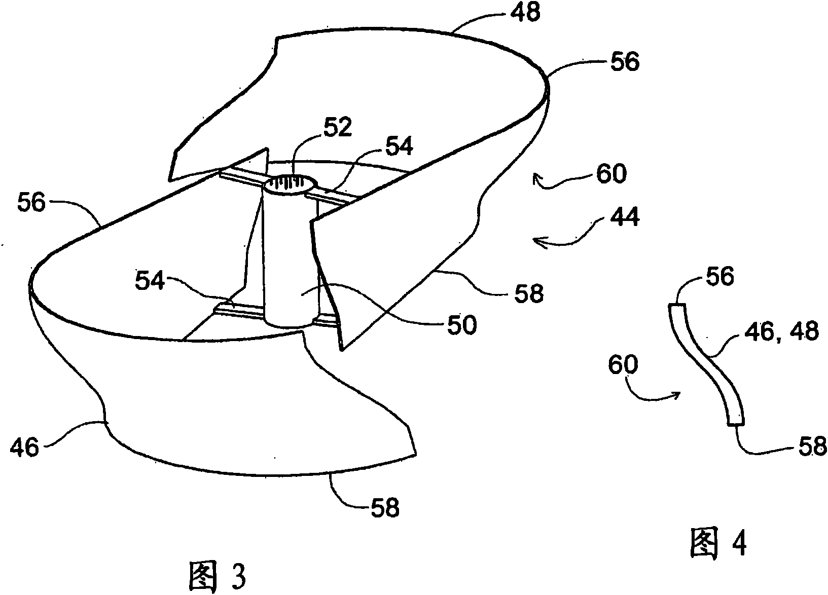
[0028] By referring to the drawings especially figure 1 , figure 2 and Figure 8 , will best understand the invention. In the embodiment shown, the device 20 has a base 22 which can be covered with a conical skirt 24 for appearance. Included in the structure of base 22 are bearings 26 and 28 . A strut 30 arranged radially around the base 22 is attached at the top end to the base and extends diagonally downward. Although for clarity in Figure 8Only two of the struts 30 are shown in , but clearly at least three such struts, preferably four to eight, will be required to fully support the apparatus. Typically, the poles will be equally spaced around the base 22 of the device, but unequal spacing may be used if the device is to be mounted on particularly uneven ground. The strut 30 will be attached at its lower end to a ground engaging structure 32 which may take the form of a circular or polygonal flat plate, or may be a radially projecting rod to which the lower end of th...


PUM


Abstract

A vertical wind-driven electricity generation device and rotor design is described, which utilizes a unique segmented Savonius rotor and which is easily handled, transported, assembled and maintained,even by a single person. The blades of the rotor are segmented into a plurality of modest size blade pair segments, each of which comprises two (or optionally, three or four) low height, helically curved blade portions. The blade pair segments are preferably of the same height and diameter. The rotor is mounted on a central vertical shaft connected to a generator. When the plurality of blade portions are installed on the device's central shaft, the overall blade configuration functions as an unitary Savonius rotor. Flow of gas (normally air in the form of wind) causes the segmented Savonius rotor to move, turning the shaft and rotating member of the generator to rotate, causing the generator to generate electricity.

Description

technical field [0001] The invention relates to generators and segmented rotors. More particularly, the present invention relates to a generator driven by wind energy through a segmented rotor and applicable to small devices such as personal residential devices. Background technique [0002] Wind or wind-driven power plants are an important source of renewable electrical energy. Some wind turbines are horizontally aligned, mounted on tall masts and resemble large propeller-equipped aircraft engines, others are vertically aligned and feature two or more elongated vertical sails shaped rotor. The present invention concerns the latter group. While many designs have been proposed or used for wind driven vertical rotors driving generators, barrel dragged rotors are rarely used. It is generally believed that lifting rotors are more efficient for large equipment, while barrel rotors are mainly used for small equipment. See, eg, JSME Int'l. J., Hayashi et al., Sequence B: 48(1)...

Claims


Application Information

Patent Timeline
Patent Type & Authority Applications(China)
IPC IPC(8): F03D9/00
CPCY02B10/30F03D3/061Y02E10/74F03D3/005F05B2240/40F05B2250/25F05B2240/213Y10T29/49002
Inventor K·摩根M·斯莱特里
Owner SAUER ENERGY
Learn More