
Electric iron improved structure

An improved structure and technology of electric irons, applied in the direction of hand irons, iron pads, washing devices, etc., can solve the problems of unsatisfactory use effect and immature ceramic bottom plate technology, and achieve good ironing effect and long service life.

Active Publication Date: 2010-03-03
NINGBO SHUAIWEI ELECTRIC APPLIANCE
View PDF1 Cites 0 Cited by
  • Summary
  • Abstract
  • Description
  • Claims
  • Application Information

AI Technical Summary

Problems solved by technology

However, the direct use of ceramic bottom plate technology is not very mature, and the use effect is not ideal.

Method used


Image

  • Electric iron improved structure
  • Electric iron improved structure
  • Electric iron improved structure

Examples


Embodiment Construction

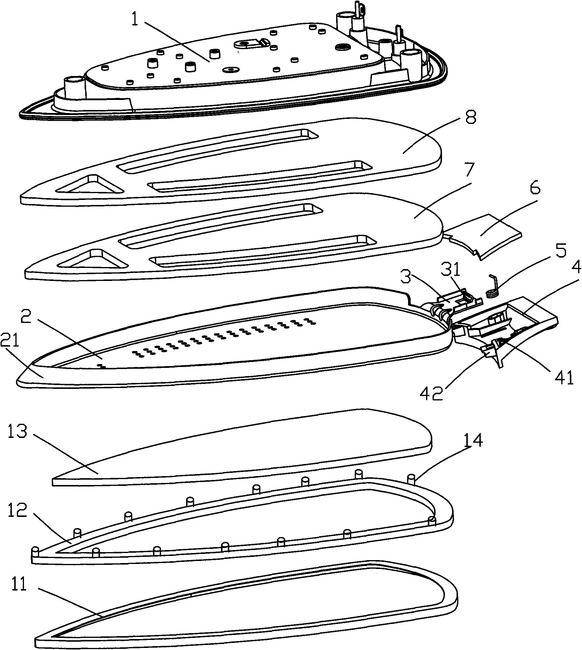
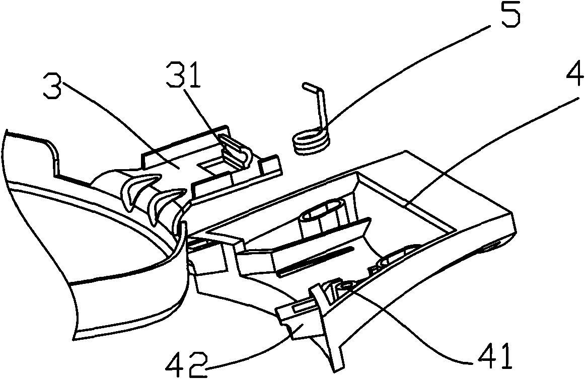
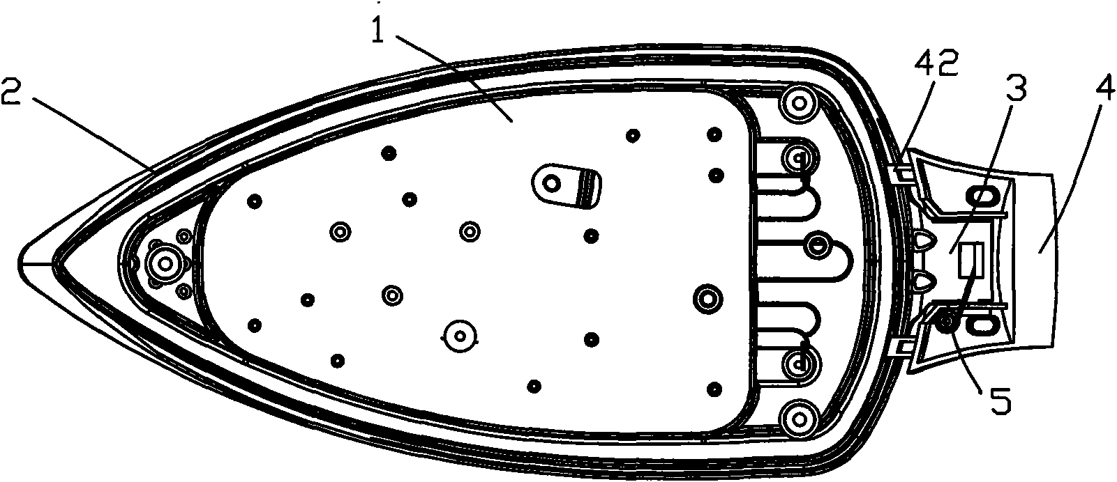
[0021] like Figure 1 to Figure 4 As shown, it is an embodiment of an improved structure of an electric iron according to the present invention, including an aluminum alloy bottom plate 1, and a ceramic plate 2 is provided at the lower part of the aluminum alloy bottom plate for easy disassembly, and the aluminum alloy bottom plate and the ceramic plate are locked by a locking device. Buckle together. The locking device includes lugs 3 at the rear of the ceramic plate, and a locking base 4 flexibly arranged on the lugs. The locking base is provided with a buckle foot 42 pressed on the rear edge of the aluminum alloy base plate. A spring 5 is provided between the lug and the buckle base to generate the pressing force of the buckle foot. The lock base is slid on the lug along the horizontal direction, the lock base is provided with a boss 41, the lug is provided with a slot 31, one end of the spring is sleeved on the boss, and the other end of the spring is snapped on the card....


PUM


Abstract

The invention discloses an electric iron improved structure which comprises a bottom board; the bottom board comprises an aluminum alloy bottom board and a ceramic board which is arranged at the lowerpart of the aluminum alloy bottom board and easily dismounted; and the aluminum alloy bottom board and the ceramic board are locked together by a locker. The locker comprises a convex lug at the sidepart of the ceramic board and a locking base sliding on the convex lug along the horizontal direction; the locking base is provided with a locking pin which is pressed on the edge at the back side ofthe aluminum alloy bottom board; a spring generating a pressing force of the locking pin is arranged between the convex lug and the locking base; a convex column is arranged on the locking base; a clamping slot is arranged on the convex lug; and one end of the spring is sheathed on the convex column and the other end thereof is clamped in the clamping slot. As the technical scheme is adopted by the electric iron improved structure, when ironing common fabric, the aluminum alloy bottom board can be used and the ceramic board can be mounted when ironing fine fabric; therefore, the electric ironimproved structure has the advantages of the aluminum alloy board and the ceramic board concurrently, and has the characteristics of long service life and good ironing effect.

Description

technical field [0001] The invention relates to an improved structure of an electric iron, in particular to an improved structure of the bottom plate of the electric iron. Background technique [0002] More than 90% of electric iron soleplates on the market now adopt aluminum alloy material, and its hardness is very low, only about hardness HB30-35, wear resistance is relatively poor, and aluminum alloy soleplate is not suitable for ironing delicate fabrics. In order to solve this problem, some companies are now spraying a layer of ceramic wear-resistant layer on the aluminum alloy bottom plate of the electric iron to improve its wear resistance. Since ceramics have the advantages of good wear resistance and non-stickiness, consumers can reduce damage to clothes during ironing. However, because the sprayed ceramic layer is thin, its use time is short. In addition, a composite layer of ceramic glaze or enamel is used on the aluminum alloy bottom plate. Although the wear resi...

Claims


Application Information

Patent Timeline
IPC IPC(8): D06F75/38D06F83/00
Inventor 张建炜
Owner NINGBO SHUAIWEI ELECTRIC APPLIANCE
Learn More