Supercharge Your Innovation With Domain-Expert AI Agents!

Scroll compressor

A technology for scroll compressors and compression chambers, which is applied to rotary piston machines, rotary piston pumps, mechanical equipment, etc., can solve problems such as supply difficulties and achieve the effect of improved sealing

Inactive Publication Date: 2010-03-03
HITACHI APPLIANCES INC
View PDF1 Cites 9 Cited by
  • Summary
  • Abstract
  • Description
  • Claims
  • Application Information

AI Technical Summary

Problems solved by technology

Patent Document 1 has a problem that it is easy to supply oil to the compression chamber formed on the outer line side of the orbiting scroll, but it is difficult to supply oil to the compression chamber formed on the inner line side.

Method used


Image

  • Scroll compressor
  • Scroll compressor
  • Scroll compressor

Examples


Embodiment 1

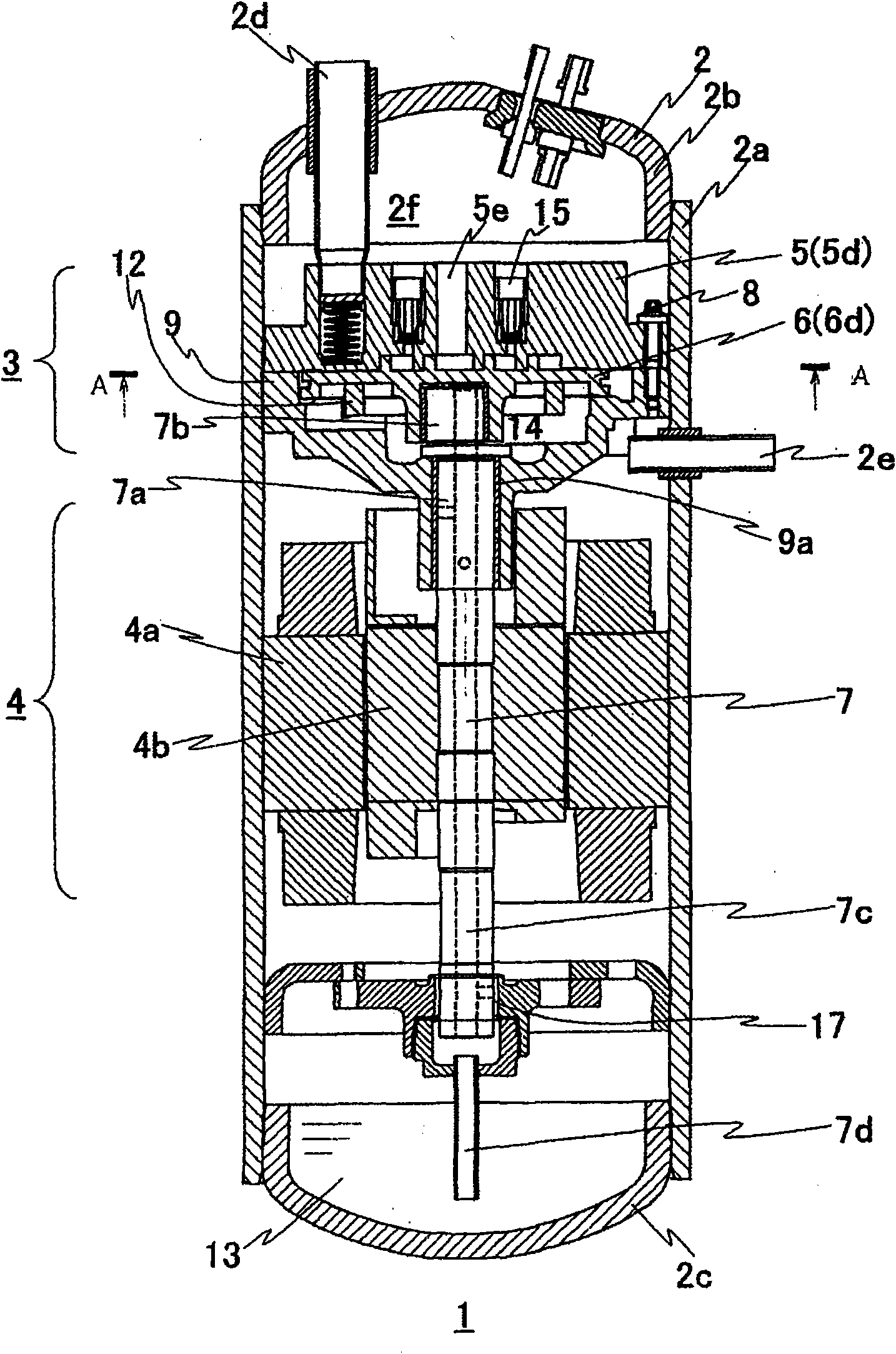
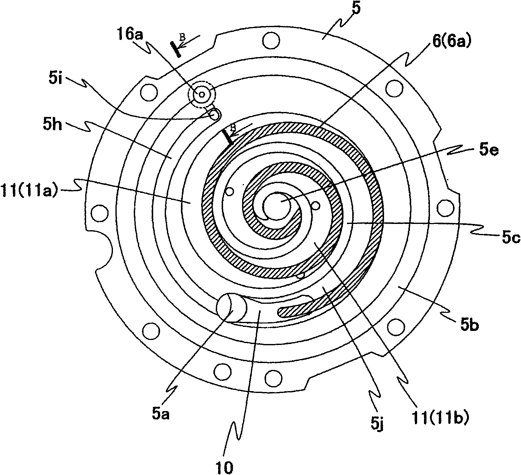
[0021] use Figure 1-Figure 8 A first embodiment of the scroll compressor of the present invention will be described. figure 1 is a longitudinal sectional view of the scroll compressor of the first embodiment, figure 2 is prior art figure 1 The A-A section diagram, image 3 yes figure 2 The B-B section diagram, Figure 4 It is an explanatory diagram when the suction of the rotary outer line chamber is completed, Figure 5 It is an explanatory diagram when the suction of the rotary inner cable chamber is completed, Figure 6 of the first embodiment figure 1 The A-A section diagram, Figure 7 yes Figure 6 The C-C section diagram, Figure 8 It is an explanatory diagram of the oil return method of the back pressure control valve of the first embodiment.

[0022] The scroll compressor 1 is provided with: a compression mechanism part 3, which is composed of an orbiting scroll 6 and a fixed scroll 5 provided with spiral scroll wraps 6a and 5c vertically; and a motor 4 th...

Embodiment 2

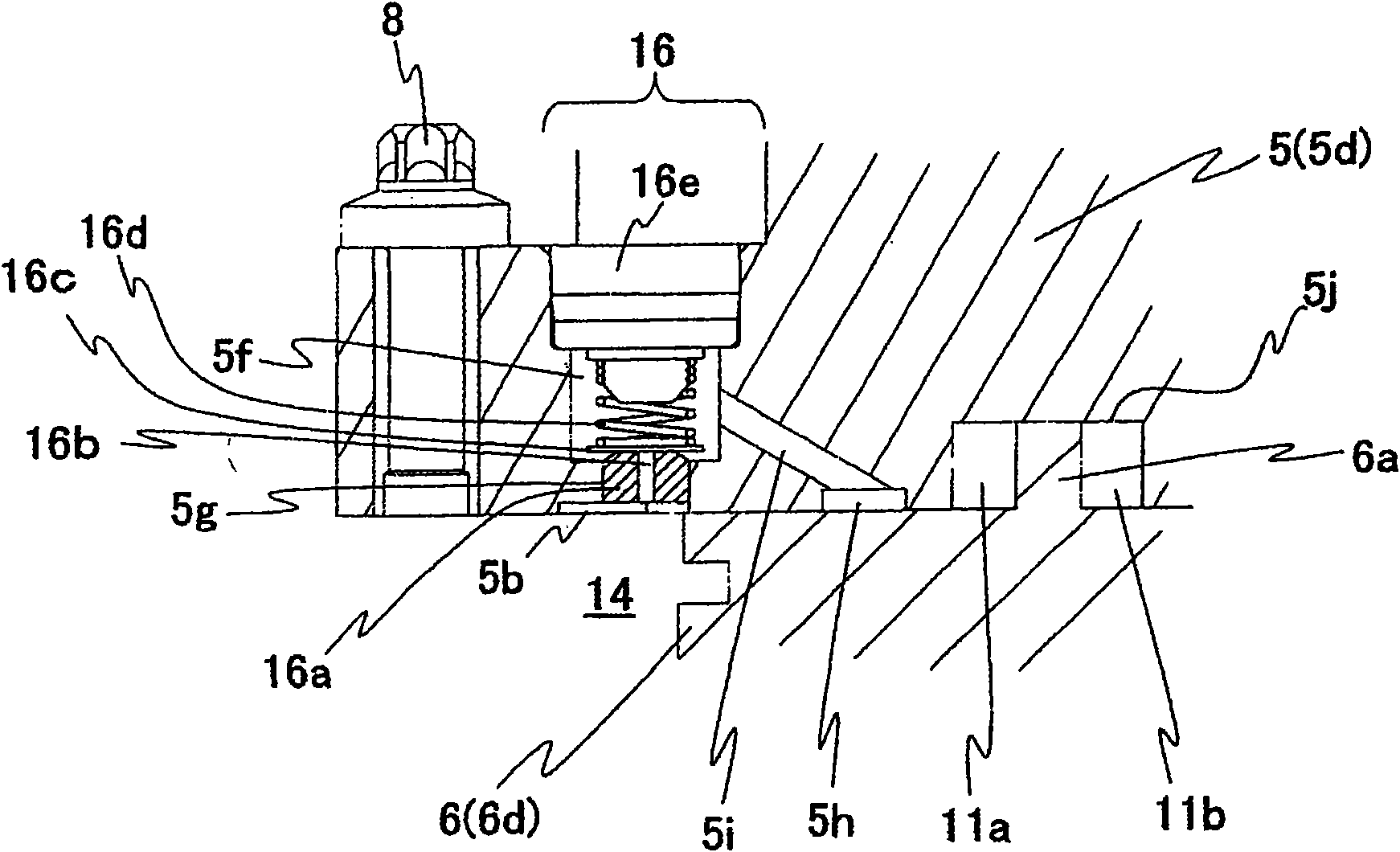
[0040] use Figure 9 A second embodiment of the present invention will be described. Figure 9 of the second embodiment Figure 6 The C-C section diagram. Here, since the basic structure is the same as that of Embodiment 1, detailed description is omitted.

[0041] The difference from the first embodiment is that the conduction path 5i connecting the spring receiving hole 5f and the dedendum surface 5j is inclined with respect to the dedendum surface 5j. By inclining the guide path 5i with respect to the dedendum surface 5j, the compressor can be easily assembled. That is, before the sealing member 16e is press-fitted, a drill is inserted through the hole of the sealing member 16e to process the conduction path 5i, and thereafter, the conduction passage 5i does not need to be formed separately when the seal member 16e is press-fitted. Assembly becomes easy without the labor and time of hole plugging.

[0042] use Figure 10 A third embodiment of the present invention wil...


PUM


Abstract

The present invention provides a scroll compressor, which can reliably supply oil to two compression chambers of an external line side and an internal line side of a rotation scroll member, and improve the sealing performance of the compression chambers. The scroll compressor of the present invention comprises: a rotation scroll member of which a bottom board comprises a vertical arranged swirl-shaped scroll; compression chambers formed by the rotation scroll member and a fixed scroll member and provided with an internal line side compression chamber at the internal line side of the rotation scroll member and an external line side compression chamber at the external line side of the rotation scroll member; a back pressure chamber arranged at the back of the rotation scroll member; and a communicating pipeline for communicating the back pressure chamber and the compression chambers and for forming two openings respectively towards the internal line side compression chamber and the external line side compression chmaber of an opening portion of the compression chamber sides.

Description

technical field [0001] The present invention relates to a scroll compressor used for compressing refrigerant gas in heat pump water heaters, air conditioners, and the like. Background technique [0002] The scroll compressor generates a force separating the two scrolls from each other through the compression action of the fixed scroll and the orbiting scroll. At this time, in order to prevent the orbiting scroll from being separated from the fixed scroll, a back pressure chamber constituting an intermediate pressure between the discharge pressure and the suction pressure is provided on the opposite side of the orbiting scroll to the fixed scroll. This back pressure presses the orbiting scroll against the fixed scroll. The back pressure is adjusted by a check valve provided on a communication path connecting the back pressure chamber and the suction chamber (for example, refer to Patent Document 1). [0003] In Patent Document 1, a pressure difference control valve composed...

Claims


Application Information

Patent Timeline
Patent Type & Authority Applications(China)
IPC IPC(8): F04C18/02
Inventor 幸野雄小山昌喜向井有吾竹林昌宽
Owner HITACHI APPLIANCES INC
Features
  • R&D
  • Intellectual Property
  • Life Sciences
  • Materials
  • Tech Scout
  • Unparalleled Data Quality
  • Higher Quality Content
  • 60% Fewer Hallucinations
Learn More