Deburring device

A deburring and spindle technology, which is applied in the direction of machine tools, grinding machines, metal processing equipment, etc., which are suitable for grinding the edge of workpieces, can solve the problems of difficult deburring and deburring, and achieve the effect of effective deburring

Inactive Publication Date: 2010-03-10
MURATA MASCH LTD
View PDF4 Cites 3 Cited by
  • Summary
  • Abstract
  • Description
  • Claims
  • Application Information

AI Technical Summary

Problems solved by technology

The deburring device of Patent Document 2 makes the two roller brushes swing forward and backward, and only needs to occupy a small area, but it cannot perform deburring from multiple directions, so it is difficult to perform effective deburring

Method used


Image

  • Deburring device
  • Deburring device
  • Deburring device

Examples


Embodiment Construction

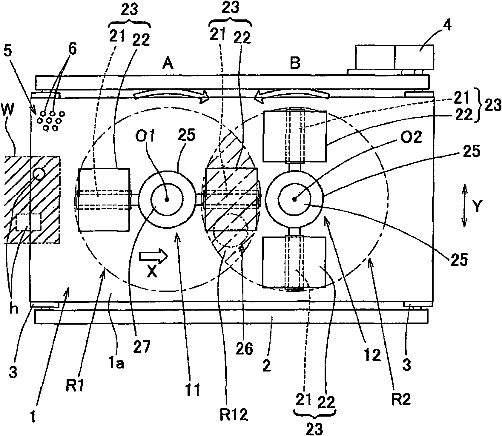
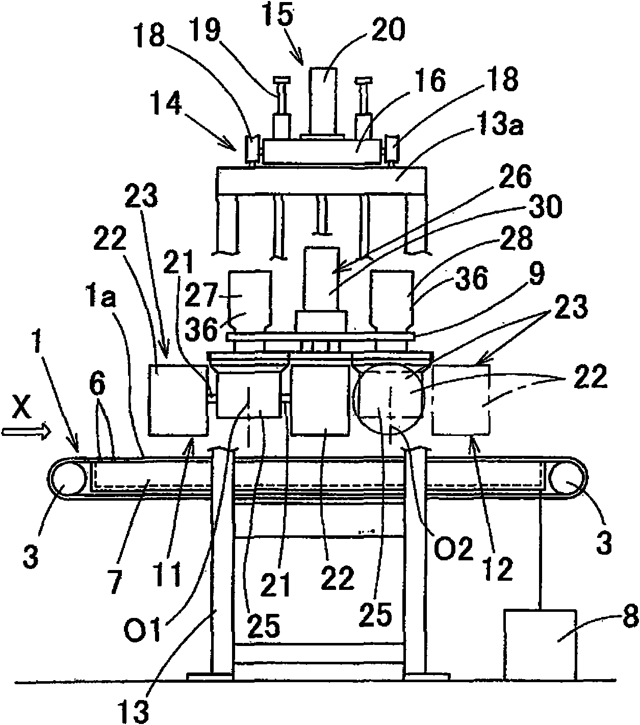
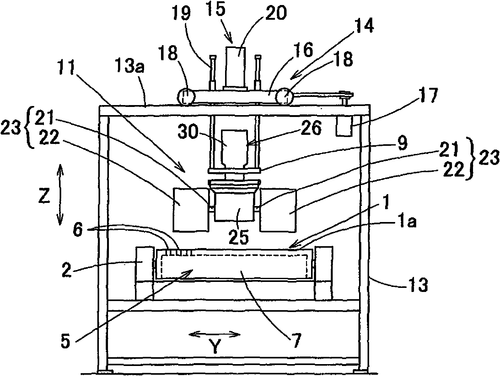
[0036] combine Figure 1 to Figure 9 , to illustrate an embodiment of the present invention. This deflashing device includes a conveyor 1 for conveying the workpiece W, and first and second deflashing heads 11 and 12 positioned above the conveyor 1 and arranged side by side in the conveying direction (arrow X direction). The workpiece W is a flat sheet such as a sheet metal, and is subjected to punching of the hole h, cutting of the outer periphery, or the like by a punch or other sheet metal processing machine. When the workpieces W are large pieces, they are arranged in a single row on the conveyor 1, and when the workpieces W are small pieces, multiple pieces are placed side by side in the width direction.

[0037] The conveyor 1 is a belt conveyor configured by hanging an endless conveyor belt 1 a on rollers 3 at front and rear ends of a conveyor frame 2 . The roller 3 at one end is driven by a drive source 4 such as a motor. The conveyor 1 is provided with a workpiece ...


PUM


Abstract

The invention provides a deburring device for effectively deburring cutting portions machined by a sheet-metal working machine and burs produced in punching machining (pores, window-shaped holes). The deburring device comprises a conveyor for conveying workpieces (W), first and second deburring heads (11, 12) arranged in parallel along a conveying direction (X) above the conveyor (1). Each deburring head comprises a plurality of horizontal main shafts (21), deburring members (22) provided on each of the main shafts (21). The plurality of horizontal main shafts can be freely rotatably arranged about vertical rotation centers (01, 02) and extends in radiation shape. The deburring member rotation areas (R1, R2) formed by the first and the second deburring heads comprises an overlapping area (R12) of the both. The first and the second deburring heads do not interference with each other and synchronously rotate along directions reversed to each other.

Description

technical field [0001] The present invention relates to a deburring device (deburring device) for removing burr generated by metal sheet processing such as cutting and punching with a punch press and other various sheet metal processing machines. Background technique [0002] In the past, the deburring device mainly used a wet-type high-speed rotating deburring head to perform deburring and grinding. Recently, a dry-type deburring device with low-speed rotating and multiple roller brushes is also used. device. In addition, it is difficult to remove the burrs of small holes and small window-shaped holes by using a dry-type low-speed rotating machine. [0003] As a proposal for such a deflashing device, it has been proposed to set a turret revolving around a vertical axis above the conveyor for conveying workpieces, and to set a plurality (for example, three) of deflashing heads at its eccentric position to present A plurality of radially extending grinding rolls constitute ...

Claims


Application Information

Patent Timeline
Patent Type & Authority Applications(China)
IPC IPC(8): B24B9/00
Inventor 市川茂治
Owner MURATA MASCH LTD
Why Eureka
Try Eureka