Puncher

A piercing device and base technology, which is applied in metal processing and other directions, can solve problems such as not having, and achieve the effect of preventing mutual misalignment and misalignment

Active Publication Date: 2013-01-02
KOKUYO CO LTD
View PDF1 Cites 0 Cited by
  • Summary
  • Abstract
  • Description
  • Claims
  • Application Information

AI Technical Summary

Problems solved by technology

[0007] However, the perforating device disclosed in Patent Document 1 has a disadvantage in that, although it is suitable for forming two holes at positions symmetrical to the above-mentioned center position, it does not have positional restrictions in the case of performing perforation several times the number of perforating tools. unit used

Method used


Image

  • Puncher
  • Puncher
  • Puncher

Examples


Embodiment Construction

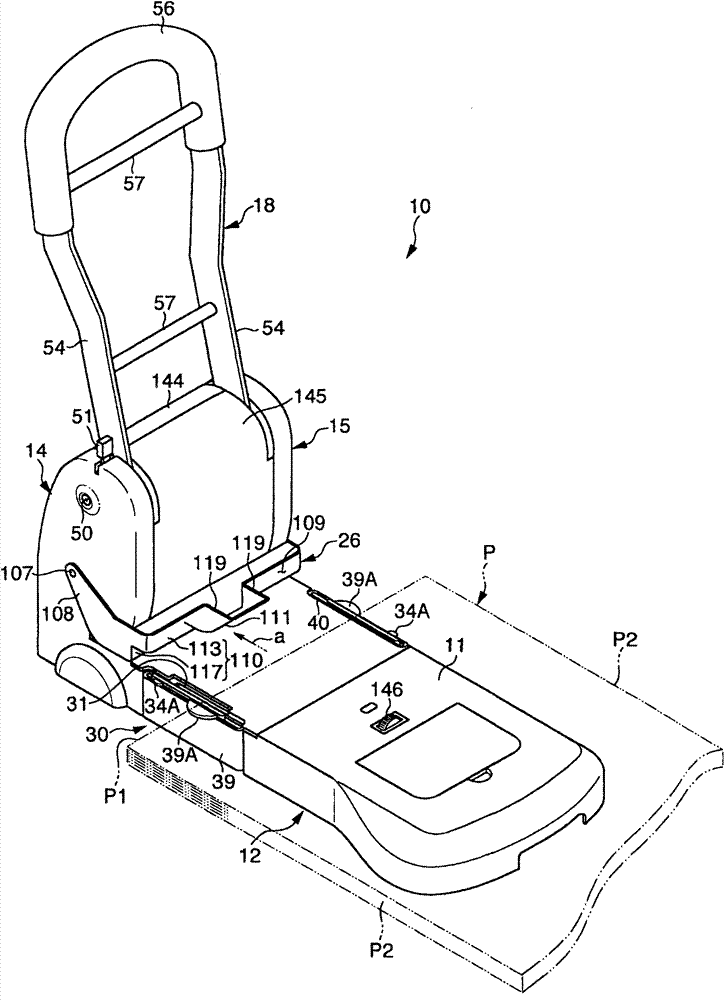
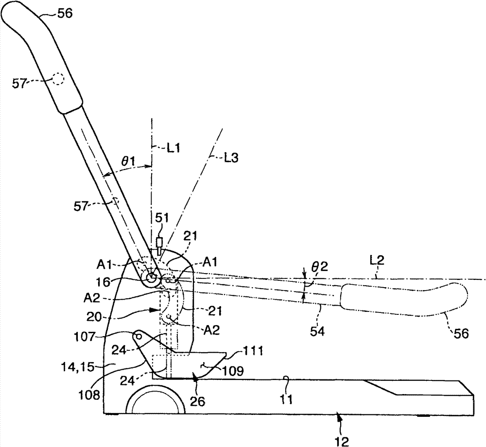
[0040] Hereinafter, preferred embodiments of the present invention will be described in more detail with reference to the accompanying drawings. In addition, in this specification, unless otherwise specified, the term indicating the direction or the position shall be figure 2 As a reference, the right side in the figure is "front", and the left side is "rear". In addition, the vertical direction of the paper in the figure is "left and right", the front side is "left", and the inward side is "right".

[0041] Again, if figure 1 As shown, the so-called "non-operating time" is used for the case where the operating lever is at the release limit away from the base, and the position of the operating lever at the release limit is regarded as the "initial position". In addition, "at the time of piercing" means that when the tip of the piercing blade touches the base side and passes through the paper, the position of the operating lever at this time is the "lodging position". In ad...


PUM


Abstract

The invention provides a puncher forming punch holes more than the number of punching blades along the end edge of paper sheets and accurately specifying positions where the punch holes are to be formed. This puncher (10) comprises: a base (12) having a support surface (11) for a sheet of paper (P); the punch blades (24) for punching the sheet (P); and an operation lever (18) for vertically moving the punch blades (24). A position restraining member (31) mounted on the base (12) disappearably to the upper surface side. The position restraining member (31) restrains the position of the side end edge (P1) of the sheet (P) perpendicular to the insertion side end edge (P1) thereof so that the punch holes of two times the number of the punch blades (24) can be formed in the positions symmetrical with respect to the center of the insertion side end edge (P1). A centering member (30) is provided in the base (12), and used as an extended support surface.

Description

technical field [0001] The present invention relates to a kind of perforation device, more specifically, it is about a kind of perforation that can carry out twice the number of perforation knives on paper, and can correctly designate the formation position of this perforation, and reliably make the corresponding Consistently positioned piercing device. Background technique [0002] In the filing and sorting of book documents, it is a known technique to form binding holes at a plurality of positions along one edge of the paper, and to insert binding feet or binding rods of a binding tool into the binding holes. When performing such binding of paper, a commercially available punching device is used to punch a binding hole on the edge side of the paper. [0003] The structure adopted by the general perforating device is: there are two perforating knives, and the perforating knives are pressed down by rotating the operating lever to perforate. In this case, in order to align ...

Claims


Application Information

Patent Timeline
Patent Type & Authority Patents(China)
IPC IPC(8): B26F1/02B26D7/01B26D5/10B26D7/26B26F1/14
Inventor 篠原胜增山正明
Owner KOKUYO CO LTD
Why Eureka
Try Eureka