Injection controlling device and injection controlling method

A control device and control method technology, applied in the field of injection control devices, can solve problems such as burrs, quality degradation of molded products, and maintenance of mold internal pressure

Active Publication Date: 2010-03-10
SUMITOMO HEAVY IND LTD
View PDF1 Cites 6 Cited by
  • Summary
  • Abstract
  • Description
  • Claims
  • Application Information

AI Technical Summary

Problems solved by technology

[0011] However, in the above-mentioned conventional injection device, it is difficult to maintain the internal mold pressure at an appropriate value when the ho

Method used


Image

  • Injection controlling device and injection controlling method
  • Injection controlling device and injection controlling method
  • Injection controlling device and injection controlling method

Examples


Embodiment Construction

[0034] Hereinafter, embodiments of the present invention will be described in detail with reference to the drawings.

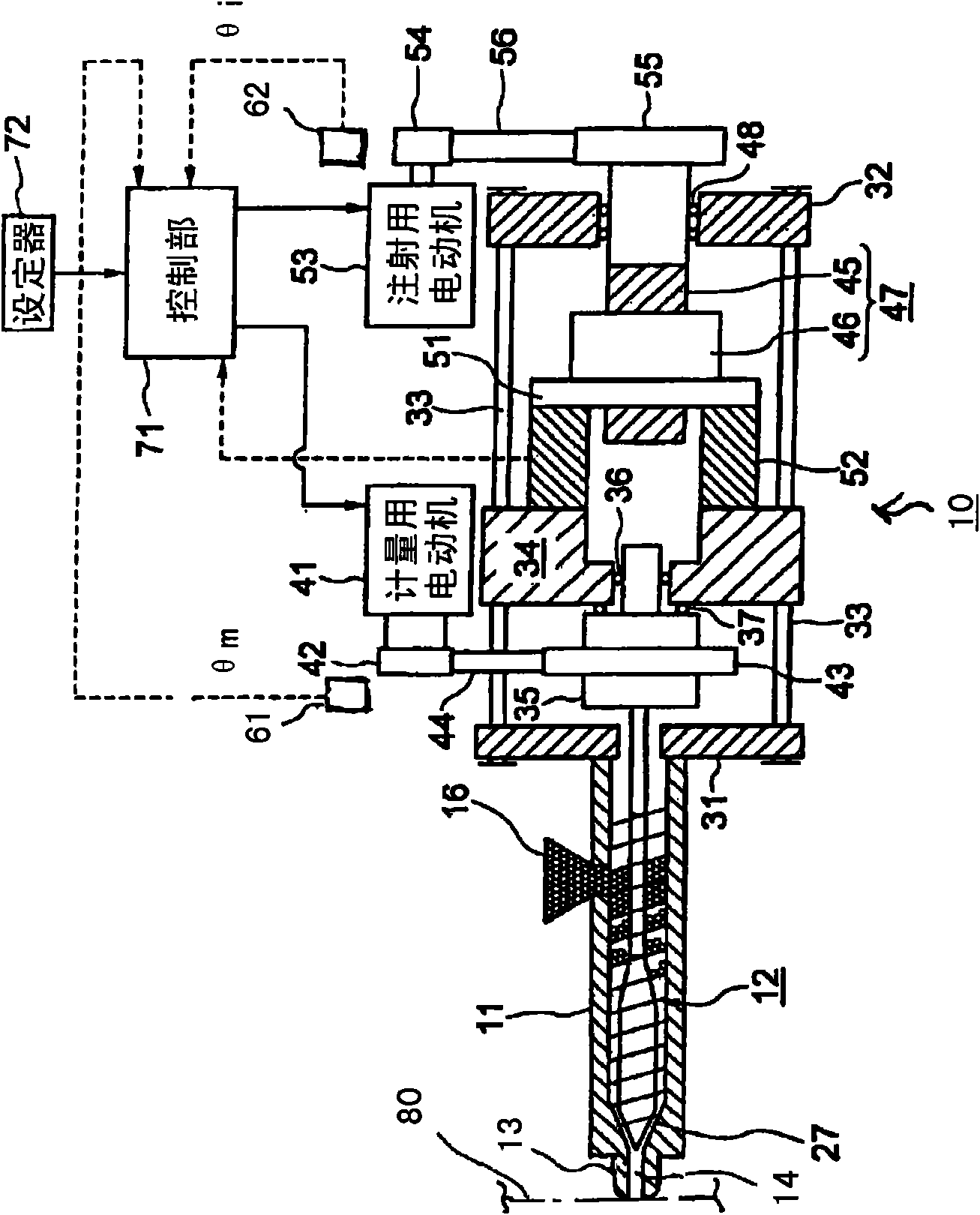
[0035] image 3 It is a conceptual diagram of the injection device according to the first embodiment of the present invention.

[0036] In the figure, 10 is an injection device, 11 is a heating cylinder as a cylinder member, 12 is a screw as an injection member disposed in the heating cylinder 11 so as to be rotatable and to advance and retreat freely, and 13 is an injection molding machine arranged at the front end of the heating cylinder 11. Nozzle 14 is a nozzle opening formed on the injection nozzle 13, and 16 is a hopper attached to a resin supply port formed near the rear end of the heating cylinder 11 to accommodate resin as a molding material and supply it into the heating cylinder 11. The screw 12 has a screw head 27 at its tip.

[0037] Heaters (not shown) for heating the resin through the heating cylinder 11 are disposed on the outer periphery of ...


PUM


Abstract

The invention provides an injection controlling device capable of maintaining the mold internal pressure as an appropriate value when the filling of the molding material is finished, and improving the quality of the molding product. The device comprises an injection member equipped in the cylinder member; a driving portion for injection for pushing the injection member forward; and a control portion (71) for controlling the driving portion in order to drive the injection member from an injection starting position to a speed control termination position. The control portion (71) performs control so that the volume of the forming material pushed into the injection member is a pushing amount of Ws during the period that the injection member is push from the injection starting position forward to the speed control termination position, Ws is larger than Wm1 when setting the volume of the forming material introduced into the die cavity space from the inlet of the mold device when the injection member reaches the speed control termination position. Before the complete filling of the forming material is performed, the injection member is stopped at the speed control termination position,so that the mold internal pressure is maintained as an appropriate value.

Description

technical field [0001] The invention relates to an injection control device and an injection control method. Background technique [0002] Conventionally, in a molding machine, such as an injection molding machine, resin, which is a molding material that is heated and melted in a heating cylinder, is injected into a cavity space of a mold device at high pressure, and the cavity space A molded article can be obtained by internal cooling and solidification. [0003] For this purpose, the injection molding machine includes a mold clamping device, an injection device, and the mold device. The mold clamping device includes a fixed die plate and a movable die plate, and the movable die plate is moved forward and backward by a mold clamping cylinder to close the mold device. , Mold closing and mold opening. [0004] On the other hand, the injection device includes the heating cylinder, an injection nozzle disposed at the front end of the heating cylinder, a screw that is freely r...

Claims


Application Information

Patent Timeline
IPC IPC(8): B29C45/77
CPCB29C2945/76665B29C2945/76882B29C2945/76187B29C2945/76083B29C45/77B29C2045/1792B29C2945/76381B29C2945/76498B29C2945/76575B29C2945/76404B29C2945/76735
Inventor 山下秀树早崎宽朗
Owner SUMITOMO HEAVY IND LTD
Why Eureka
Try Eureka