
Medical manipulator system

A medical and manipulator technology, applied in the field of medical manipulator systems, can solve problems such as time extension

Active Publication Date: 2012-05-30
OLYMPUS CORP
View PDF5 Cites 0 Cited by
  • Summary
  • Abstract
  • Description
  • Claims
  • Application Information

AI Technical Summary

Problems solved by technology

[0007] Therefore, in the medical manipulator described in Japanese Patent Application Laid-Open No. 8-224248, the bending state for holding the forceps (each arm) and the state of the holding forceps (each arm) recognized by the operator according to the operating state of the active side manipulator ( The initialization processing of the bending state matching of each arm) must be performed beforehand before the treatment of the desired part, and as a result, the problem that the time required for the treatment of the desired part is prolonged

Method used


Image

  • Medical manipulator system
  • Medical manipulator system
  • Medical manipulator system

Examples


Embodiment Construction

[0027] Hereinafter, embodiments of the present invention will be described with reference to the drawings.

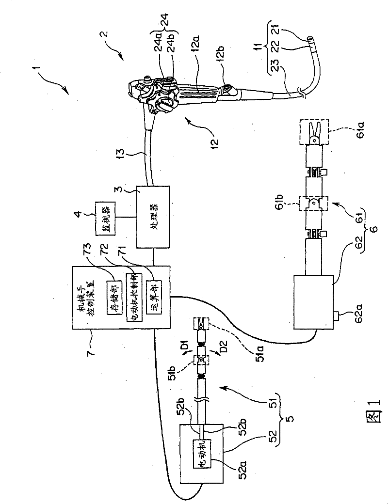
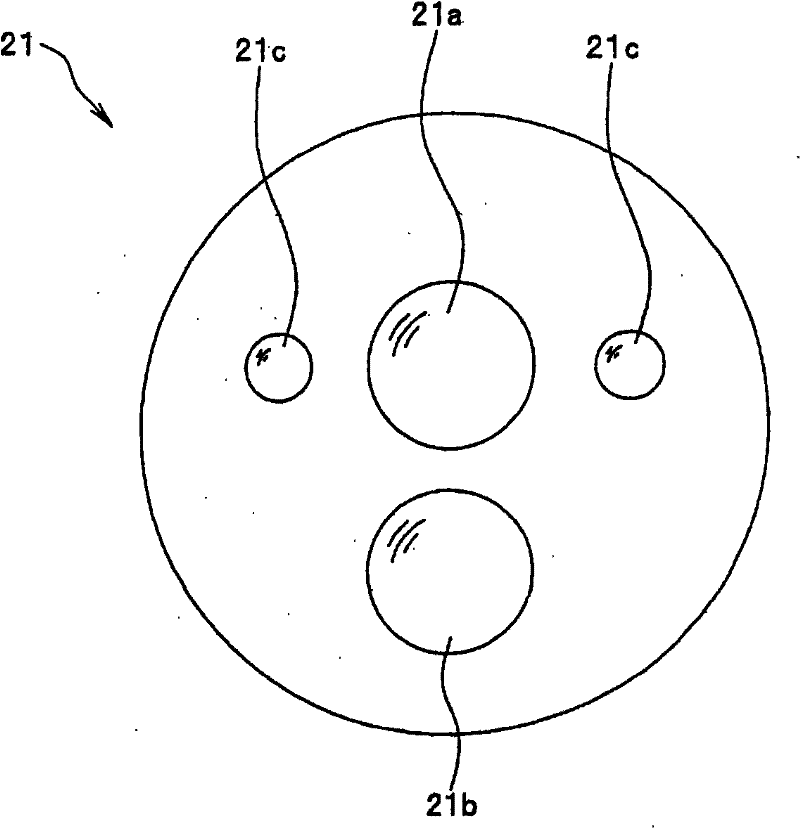
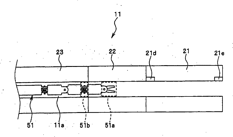
[0028] Figure 1 to Figure 13 It relates to an embodiment of the present invention. figure 1 It is a figure which shows an example of the main part structure of the medical manipulator system which concerns on embodiment of this invention. figure 2 is showing figure 1 An example of the structure of the front end surface of the front end portion of the endoscope. image 3 It is a diagram showing a situation when the robot arm portion of the slave-side robot is inserted into the treatment tool channel provided in the endoscope. Figure 4 It is a figure which shows an example of the bending state of a bending part at the time of acquiring the information concerning the rotation amount (rotation angle) of a 1st motor. Figure 5 It is a figure which shows an example of the bending state of a bending part at the time of acquiring the information concerning the rotation a...


PUM


Abstract

A medical manipulator system of the present invention includes: a medical instrument having a shape insertable into an elongated tube passage and in which one or a plurality of flexion portions are provided; a flexing actuator for supplying a driving force to flex the flexion portion; an actuator control section for controlling the flexing actuator; a detecting section provided inside the tube passage to output a detection signal when detecting that the flexion portion passes therethrough; and a computing section for performing computation to match a flexed state of the flexion portion passingthrough the detecting section to an operating state of an operation portion operable to flex the flexion portion based on an operation amount of the flexing actuator detected when the detection signal is inputted.

Description

technical field [0001] The present invention relates to a medical manipulator system, and more particularly to a medical manipulator system used for treating various organs in a living body. Background technique [0002] Endoscopes have conventionally been widely used in industrial fields, medical fields, and the like. In particular, endoscopes in the medical field are mainly used for observation and treatment of various organs in the living body. [0003] On the other hand, when using the above-mentioned endoscope to treat various organs in the living body, a treatment tool such as forceps having an elongated shape corresponding to the shape of the endoscope is used together. [0004] Furthermore, as a treatment tool for making it easier to approach a desired part of the living body as a treatment target among the above-mentioned treatment tools, for example, a medical manipulator described in Japanese Patent Application Laid-Open No. 8-224248 has been proposed. There are...

Claims


Application Information

Patent Timeline
Patent Type & Authority Patents(China)
IPC IPC(8): A61B17/00A61B17/94A61B1/005
CPCA61B2019/2242A61B17/29A61B1/00133A61B2019/4857A61B19/22A61B2019/462A61B1/018A61B2017/2908A61B34/70A61B34/71A61B2090/062A61B2090/0811
Inventor 吉江方史万寿和夫
Owner OLYMPUS CORP
Learn More