Workpiece step conveying driving system

A step-by-step conveying and driving system technology, used in conveyors, fluid-driven clutches, non-mechanical-driven clutches, etc., can solve the problems of limited bearing capacity of one-way clutch elements, non-compliance with modern environmental protection requirements, and unstable operation. Guarantee stepping accuracy, operation reliability and stability requirements, reliable technical support and guarantee, accurate and reliable clutch effect

Inactive Publication Date: 2013-01-16
CHANGCHUN EQUIP TECH RES INST
View PDF0 Cites 0 Cited by
  • Summary
  • Abstract
  • Description
  • Claims
  • Application Information

AI Technical Summary

Problems solved by technology

In a modern large-scale automated production line, if there are many stepping stations on a workpiece stepping conveyor line, the conveying distance is very long and the conveying load is heavy, if the large-bore cylinder is still used as the driving actuator in the above-mentioned conventional method, it will not only increase the number of steps The response time of the movement affects the production efficiency, and the operation is very unstable, it is easy to produce crawling phenomenon, and it will make a lot of noise, which is neither economical nor meets the modern environmental protection requirements.
For the stepping drive mechanism using one-way clutch, due to the limited carrying capacity of the one-way clutch element, it cannot meet the requirements of large-load stepping transportation, and the use of one-way clutch is prone to cumulative errors, which cannot ensure repeated positioning of stepping transportation Accuracy, only suitable for occasions that do not require high stepping accuracy
[0004] At present, the known drive devices for step-by-step delivery of workpieces also use electric motors as the drive source, and realize the step function through intermittent motion mechanisms (such as Malta mechanism), parallel four-bar linkage mechanism or other similar translation mechanisms, but due to the structural Due to the limitation of space size and specification, and without power clutch function, this kind of driving mechanism is usually used in the occasion of continuous stepping conveying of small and medium loads in short distances. The stepping cycle is fixed and cannot be adjusted in real time according to the actual needs of the site. control

Method used


Image

  • Workpiece step conveying driving system
  • Workpiece step conveying driving system
  • Workpiece step conveying driving system

Examples


Embodiment Construction

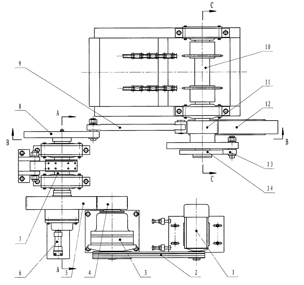
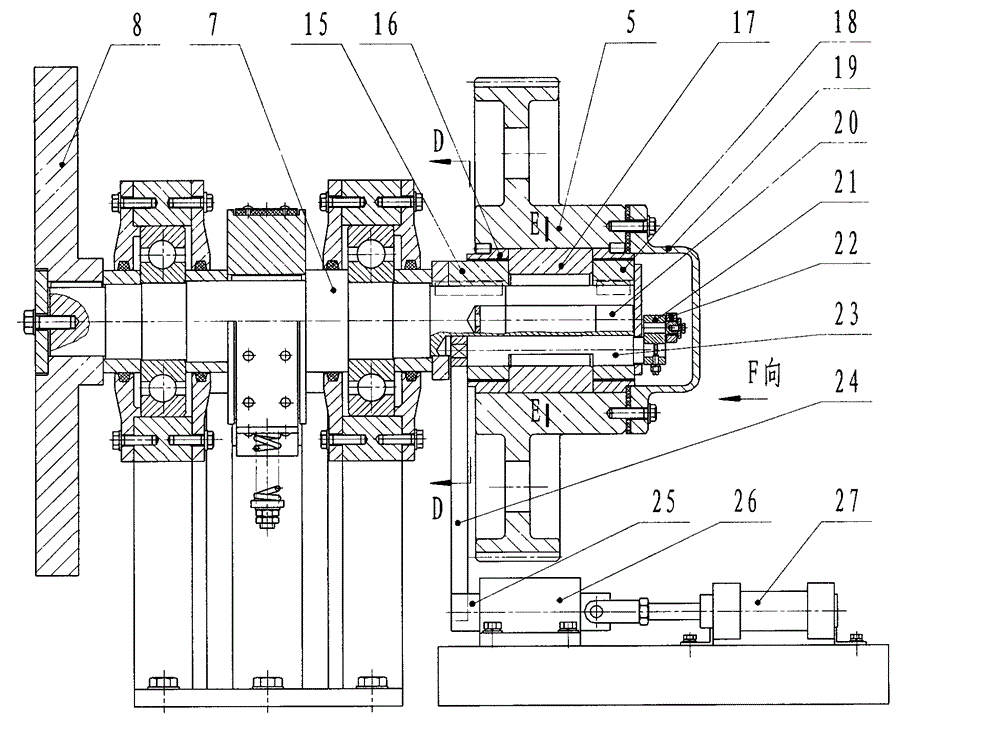
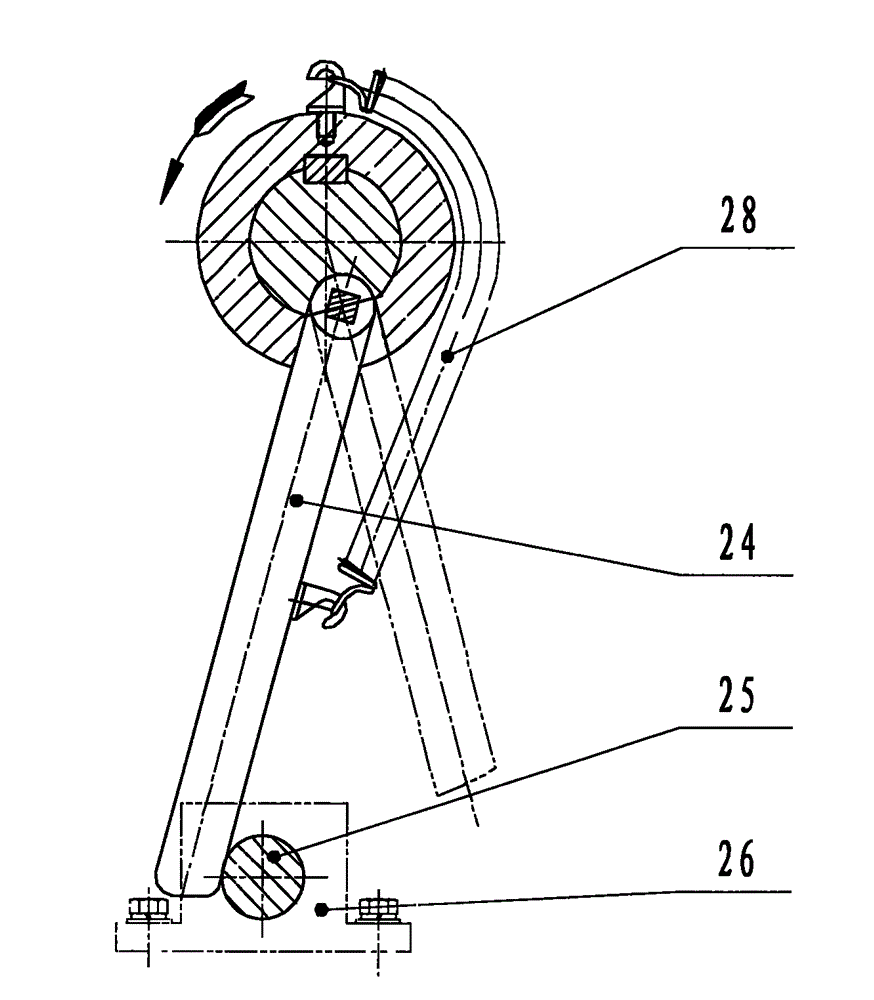
[0035] In the embodiment shown in Figure 1, the workpiece stepping conveying drive system is composed of the motor (1) through the meshing pair consisting of the belt drive (2), the reducer (3), the pinion gear (4) and the bull gear (5). The power drive part realizes the three-stage deceleration function. With the motor as the driving source, as long as sufficient power is selected, it can not only meet the large load requirements of stepping transportation, but also overcome many unfavorable factors caused by selecting other action actuators as the power source; through three-stage deceleration, a suitable The reduction ratio meets the beat and production efficiency requirements of stepping conveying. The large gear (5) realizes the power engagement and separation with the transmission shaft 1 (7) through the double-turn key clutch device installed inside it, and drives the eccentric wheel (8), connecting rod ( 9) and the slider crank mechanism formed by the rack (12), the r...


PUM


Abstract

The invention relates to a workpiece step conveying driving system which can realize a step conveying function, which is applied to the field of workpiece step conveying production in a large automatic production line, can overcome and make up the defects of a prior conveying technology on the multistation, long distance and heavy load conveying capacity, sufficiently ensure the requirements on step precision as well as reliability and stability of running and flexibly control the step working rhythm on site. The system comprises a power-driving part, double rotor clutch devices and a driven part, wherein the power-driving part takes a motor as a power source and can meet the requirements on step rhythm and production efficiency through three-level speed reduction; the driven part can achieve the step driving function, stop accumulated errors and ensure the step precision and the running stability through the function combination of a slider-crank mechanism, a rack and spur gear mechanism and a ratchet-and-pawl mechanism; and the rotor clutch devices realize rigid joint and separation of the driving part and the driven part of the system through double rotors and ensure the requirements on reliable use and precision.

Description

technical field [0001] The invention relates to a driving device for step-by-step delivery of workpieces, and is especially suitable for step-by-step delivery of workpieces in the production occasion of multi-station, heavy-load and long-distance delivery in a large-scale automatic production line. Background technique [0002] In the automatic production line, step-by-step conveying is one of the most commonly used workpiece conveying methods. For the driving device for step-by-step conveying workpieces, it can be divided into motor-driven type and pneumatic-hydraulic actuator-driven type from the power drive mode, and can be divided into clutch function type and non-clutch function type from the power connection mode. In the actual production, the appropriate power drive mode and power connection mode can be used according to the actual needs and requirements to achieve specific functions, so as to better meet the actual needs of process and sequence actions in actual prod...

Claims


Application Information

Patent Timeline
Patent Type & Authority Patents(China)
IPC IPC(8): B65G25/02F16D25/08
Inventor 康战张广平刘劲松聂凤明王大森吴庆堂闫晓丽胡宝共
Owner CHANGCHUN EQUIP TECH RES INST
Why Eureka
Try Eureka