A manual lifting device with automatic clutch

The technology of a clutch device and a lifting device is applied in the manual mechanism, the control mechanism of the wing leaf, the door/window accessories, etc., which can solve the problems of unbalance, easy disengagement of the clutch, and difficulty in engagement, and achieves the effect of convenient operation and reliable clutch.

Active Publication Date: 2011-12-21
漳州市杰龙机电有限公司
View PDF0 Cites 0 Cited by
  • Summary
  • Abstract
  • Description
  • Claims
  • Application Information

AI Technical Summary

Problems solved by technology

This method solves the problem of inconvenient operation separately. Since the mechanical plate concave-convex clutch is used, and it is in a rotating state, it is difficult to join; the tension of the welding chain is limited by the structure and deviates from the leverage point, and the additional torque is affected by the lever action. Mechanical interference is prone to occur, and manual operation is unbalanced...; After the manual opening and closing is completed, the structure uses a spring to disengage the clutch mechanism. During the manual opening and closing, the clutch is always directly affected by the force of the spring and cannot automatically lock, so when the welding chain tension changes or the chain jumps, the clutch is easy to disengage, and it is difficult to adapt to a large lifting force

Method used


Image

  • A manual lifting device with automatic clutch
  • A manual lifting device with automatic clutch
  • A manual lifting device with automatic clutch

Examples


Embodiment Construction

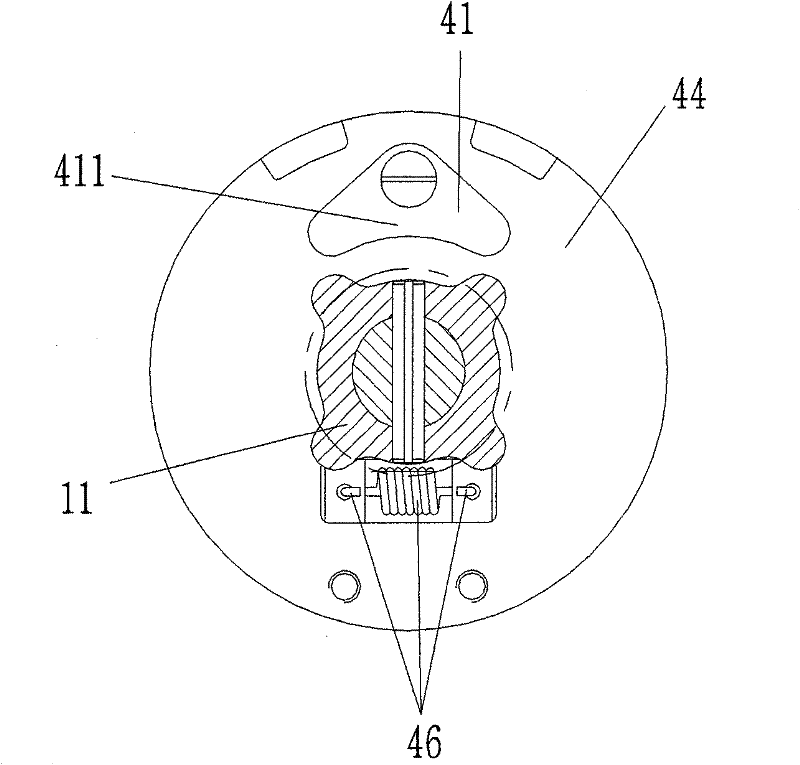
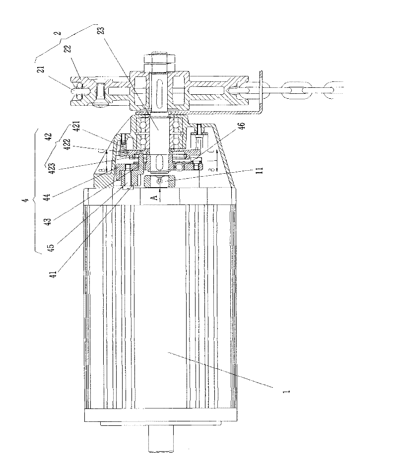
[0032] Such as figure 1 Shown is a hand-pulled lifting device with automatic clutch, which includes a motor 1, a manual rotating device 2, a motor power switch 3, and a clutch device 4; There is a radial overlapping section at the end, the overlapping section 41 of the clutch device 4 is provided with an engaging portion A and a disengaging portion 411, and the overlapping section 11 at the output end of the motor 1 is provided with an engaging portion B; the manual rotating device 2 is synchronized with the clutch device 4 Rotate; the clutch device 4 includes: a driving disc 44, a swing arm 43, a reset device 42, a pin 45; the reset device 42 includes: a back-moving spring 421, a reset disc 422, a damping ring 423; There is a tension spring 46 to reset the swing arm 43 .

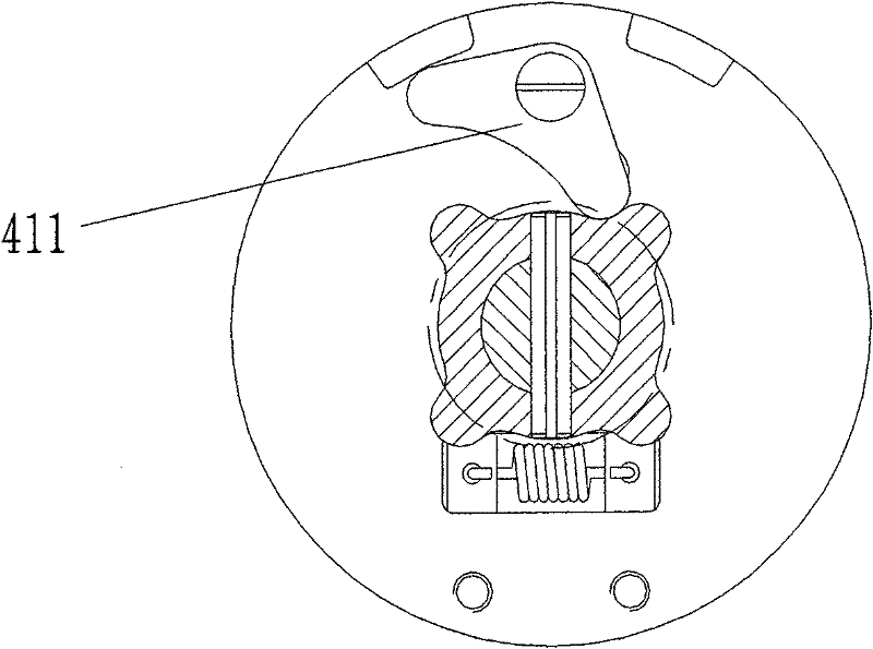
[0033] Such as figure 2 As shown: when the clutch device 4 rotates until the disengagement part 411 is facing the overlapping section 11 of the output end of the motor 1, any rotation of the output end o...


PUM


Abstract

The invention provides a manual lifting device with automatic clutch, which is characterized in that it includes a motor, a manual rotating device, a power switch of the motor, and a clutch device; the output end of the clutch device and the motor are at the ends close to each other There is a radial overlapping section, the overlapping section of the clutch device is provided with an engaging part A and a disengaging part, and the overlapping section at the output end of the motor is provided with an engaging part B; the clutch device has at least one installation position and simultaneously satisfies: "the manual rotation The device rotates synchronously with the clutch device" or "when the clutch device rotates to the overlapping section where the disengagement part is facing the motor output end, any rotation of the motor output end will not collide with the clutch device" or "the clutch device rotates at a certain angle to achieve meshing Engagement of Part A and Engagement Part B". Through the cooperation of the meshing part and the disengaging part, the present invention makes the hand-pulling action lag behind the motor action, so it is possible to achieve the effect of first disconnecting the power and then connecting the motor with one action, effectively providing a reliable clutch, convenient operation, and one-step manual operation. The clutch control mechanism that realizes motor power control and door curtain opening and closing.

Description

technical field [0001] The invention relates to a clutch device for an industrial door machine or a switch machine, in particular to a clutch operating mechanism in a rolling door machine that realizes motor power control and door curtain opening and closing manually in one step. Background technique [0002] Usually, the industrial door driver completes the opening and closing of the industrial door by electric power, and the manual opening and closing mechanism and the power shaft are in a state of disengagement; when there is a power failure or failure, the manual mechanism is connected through the clutch operation, and the door curtain is opened and closed by manual operation. [0003] For manual opening and closing and its clutch control mechanism, at present, foreign products are independent in mechanism and need to be operated step by step: engagement - manual opening and closing - disengagement, three-step cycle. Domestic products have a design that links the manual ...

Claims


Application Information

Patent Timeline
Patent Type & Authority Patents(China)
IPC IPC(8): E05F11/54
Inventor 洪俊龙
Owner 漳州市杰龙机电有限公司
Why Eureka
Try Eureka