A deceleration clutch of an intelligent washing machine

A deceleration clutch and washing machine technology, applied in the field of clutches, can solve the problems affecting the service life, stability and safety of the deceleration clutch, inability to apply the large torque of a pulsator large-capacity washing machine, failure of the clutch wrapping spring, etc. Reliable action and stable torque transmission

Active Publication Date: 2017-06-09
ZHEJIANG SANXING MECHANICAL & ELECTRONICSAL STOCK
View PDF7 Cites 0 Cited by
  • Summary
  • Abstract
  • Description
  • Claims
  • Application Information

AI Technical Summary

Problems solved by technology

[0002] At present, the deceleration clutch of the pulsator type automatic washing machine generally adopts the clutch structure of the clutch spring, the torque transmission sleeve, the pawl and the ratchet wheel to realize the switching of the washing and dehydrating working conditions. The clutch clutch spring and the torque shaft sleeve are not suitable for the large torque generated by the large-capacity pulsator washing machine during washing and dehydration. After long-term use, it is easy to cause the clutch spring to fail, which in turn leads to the failure of the clutch device, which seriously affects the Reduction Clutch Life, Smoothness and Safety

Method used


Image

  • A deceleration clutch of an intelligent washing machine
  • A deceleration clutch of an intelligent washing machine
  • A deceleration clutch of an intelligent washing machine

Examples


Embodiment Construction

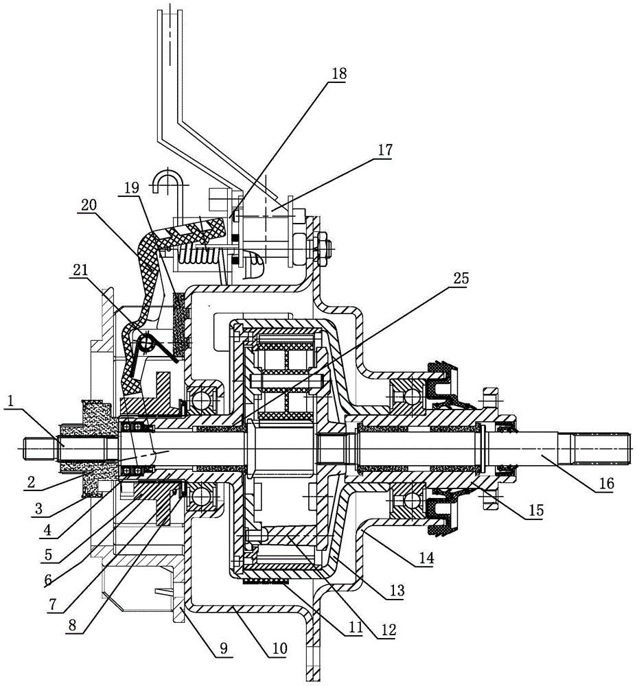
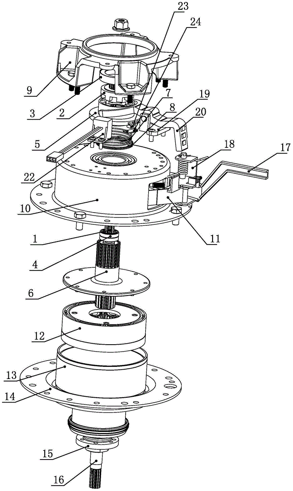
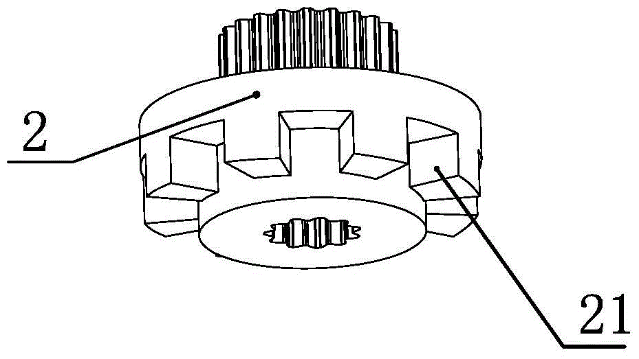
[0020] see Figure 1 to Figure 5 , a deceleration clutch for an intelligent washing machine disclosed in the present invention includes an upper housing 14, a lower housing 10, a connecting disc 5, a torque transmission sleeve 2 and a brake wheel shaft 6, and the coupling disc 5 is set on the brake wheel shaft 6 Above, a magnet 23 is set on the coupling plate 5, a Hall sensor 22 is set on the lower end surface of the lower casing 10, the position of the Hall sensor 22 matches the magnet 23, and the Hall sensor 22 There is a gap between the magnet 23; the outer surface of the brake wheel shaft 6 is provided with a first spline 61, and the inner surface of the inner hole of the coupling disc 5 is provided with a first spline 61 matching the first spline. Two splines 51, the third spline 52 is provided on the lower end of the coupling disc 5, the fourth spline 21 matching the third spline 52 is provided on the upper end of the torque transmission bushing 2, the coupling disc 5 an...


PUM


Abstract

The invention discloses a decelerating clutch of an intelligent washing machine. The decelerating clutch comprises an upper shell, a lower shell, a connection plate, a torque transmission shaft sleeve and a brake wheel axle. The connection plate is arranged on the brake wheel axle in a sleeving mode. The connection plate is provided with a magnet, a Hall sensor is arranged on the lower end face of the lower shell, the position of the Hall sensor is matched with the position of the magnet, and a gap is reserved between the Hall sensor and the magnet. First splines are arranged on the outer surface of the brake wheel axle, second splines matched with the first splines are arranged on the inner surface of an inner hole of the connection plate, third splines are arranged on the lower end portion of the connection plate, and fourth splines matched with the third splines are arranged on the upper end portion of the torque transmission shaft sleeve. A connection plate spring and a spring gland are arranged at the upper end of the connection plate. The spring gland is located at the upper end of the connection plate spring, and the spring gland abuts against the lower shell. According to the technical scheme, the decelerating clutch of the intelligent washing machine is reasonable in structural design, simple in structure, convenient to assemble, reliable in clutch action, stable in torque transmission and high in safety.

Description

technical field [0001] The invention relates to the technical field of clutches, in particular to a deceleration clutch of an intelligent washing machine. Background technique [0002] At present, the deceleration clutch of the pulsator type automatic washing machine generally adopts the clutch structure of the clutch spring, the torque transmission sleeve, the pawl and the ratchet wheel to realize the switching of the washing and dehydrating working conditions. The clutch clutch spring and the torque shaft sleeve are not suitable for the large torque generated by the large-capacity pulsator washing machine during washing and dehydration. After long-term use, it is easy to cause the clutch spring to fail, which in turn leads to the failure of the clutch device, which seriously affects the Reduction clutch life, smoothness and safety. Contents of the invention [0003] In view of the deficiencies in the prior art, the object of the present invention is to provide a deceler...

Claims


Application Information

Patent Timeline
Patent Type & Authority Patents(China)
IPC IPC(8): D06F37/30
CPCD06F37/304
Inventor 林华斌应元钞温荣耀叶克雷蔡文丰方礼群
Owner ZHEJIANG SANXING MECHANICAL & ELECTRONICSAL STOCK
Why Eureka
Try Eureka