Communication over a DC power line

A power line and electric power technology, applied in distribution line transmission systems, electrical components, wired transmission systems, etc., can solve the problems of unspecified how to modulate DC signals, multiplexing, etc., and achieve improved immunity, low power consumption, and signal high speed effect

Inactive Publication Date: 2010-03-10
科学技术设备委员会
View PDF1 Cites 2 Cited by
  • Summary
  • Abstract
  • Description
  • Claims
  • Application Information

AI Technical Summary

Problems solved by technology

However, the document does not specify how to modulate the DC signal, or how to multiplex the signal from more than one transmitter on the DC power line

Method used


Image

  • Communication over a DC power line
  • Communication over a DC power line
  • Communication over a DC power line

Examples


Embodiment Construction

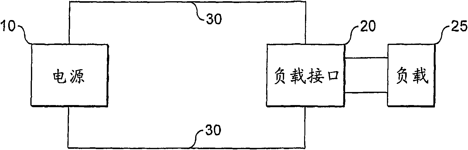
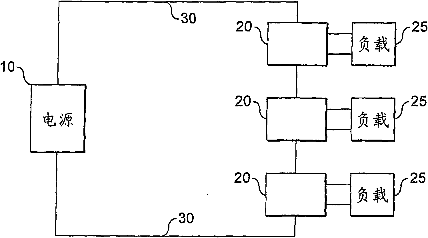
[0025] first reference figure 1 , which shows a block diagram of the system according to the invention. The system includes a power supply 10 providing power to a load interface 20 via a direct current connection 30 . The load interface 20 is connected to a load 25 .

[0026] The power supply 10 regulates the current flowing through the direct current connection 30 . Said current comprises a non-zero constant component so that a direct current flows through the connection 30 . However, the power supply 10 also causes the regulated current supplied to the connection 30 to have a varying component. This change is based on the data signal to be transmitted to the load interface 20 . This variation thus causes the current to be modulated.

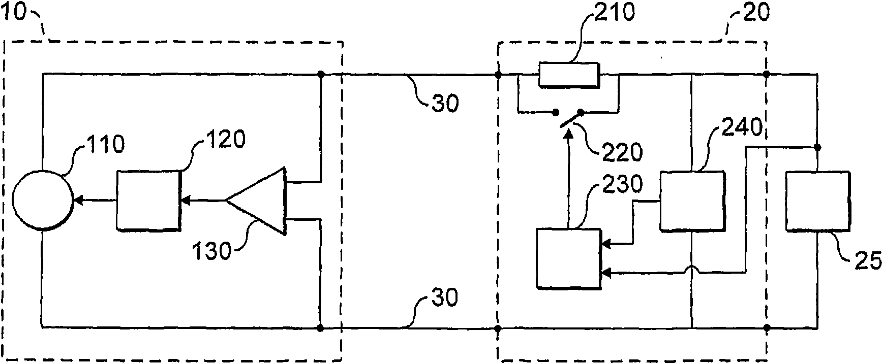
[0027] The load interface 20 draws power from the current flowing through the connection 30 . The load interface 20 provides DC power to the load 25 . It also senses the varying components of the current and demodulates the current to ob...


PUM


Abstract

A combined power and communication system, a transmitter, a receiver, and a method of communicating data over a power line are provided. A power supply is arranged to supply an output current to a power line and comprises a current source. The current source is arranged to supply a DC component to the output current and the power supply is further arranged to modulate the output current accordingto a data signal. A load interface is arranged to receive a load at load terminals, to provide DC power from the power line to the load terminals, and to demodulate the current received from the powerline to receive the data signal.

Description

technical field [0001] The present invention relates to bi-directional data communication over electrical connections carrying direct current. This can be applied eg to sensors or transducer arrays. Background technique [0002] In many applications, it is important to provide one or more devices with both power and a means for communicating data with other devices. Although these power and data connections may be provided separately, it is always desirable to provide both power and data over the same connection. This is especially beneficial where the size, weight or mass of the cable is limited or where it is desired to limit the number of connections. [0003] Techniques for communicating data over connections that provide alternating current are well known. There are also technologies that provide communication over a direct current connection. These techniques may be attractive when using multiple DC powered transducers, especially if they are distributed over a wid...

Claims


Application Information

Patent Timeline
Patent Type & Authority Applications(China)
IPC IPC(8): H04B3/54
CPCH04B3/548H04B2203/547
Inventor 马克·韦伯恩里科·朱利奥·维拉尼
Owner 科学技术设备委员会
Why Eureka
Try Eureka