Casting valve with complementary compression piston, casting device and method for die casting

A technology of casting pressure and piston, applied in the field of casting valve, can solve problems such as consumption, achieve the effect of continuous heat input and save structure space

Active Publication Date: 2018-11-09
舒乐绞扭机有限责任公司
View PDF12 Cites 0 Cited by
  • Summary
  • Abstract
  • Description
  • Claims
  • Application Information

AI Technical Summary

Problems solved by technology

The casting valve and the post-compression mechanism have to be coordinated with one another, which is complex, significantly increases the configuration of the casting device and thus increases the energy required for heating

Method used


Image

  • Casting valve with complementary compression piston, casting device and method for die casting
  • Casting valve with complementary compression piston, casting device and method for die casting
  • Casting valve with complementary compression piston, casting device and method for die casting

Examples


Embodiment Construction

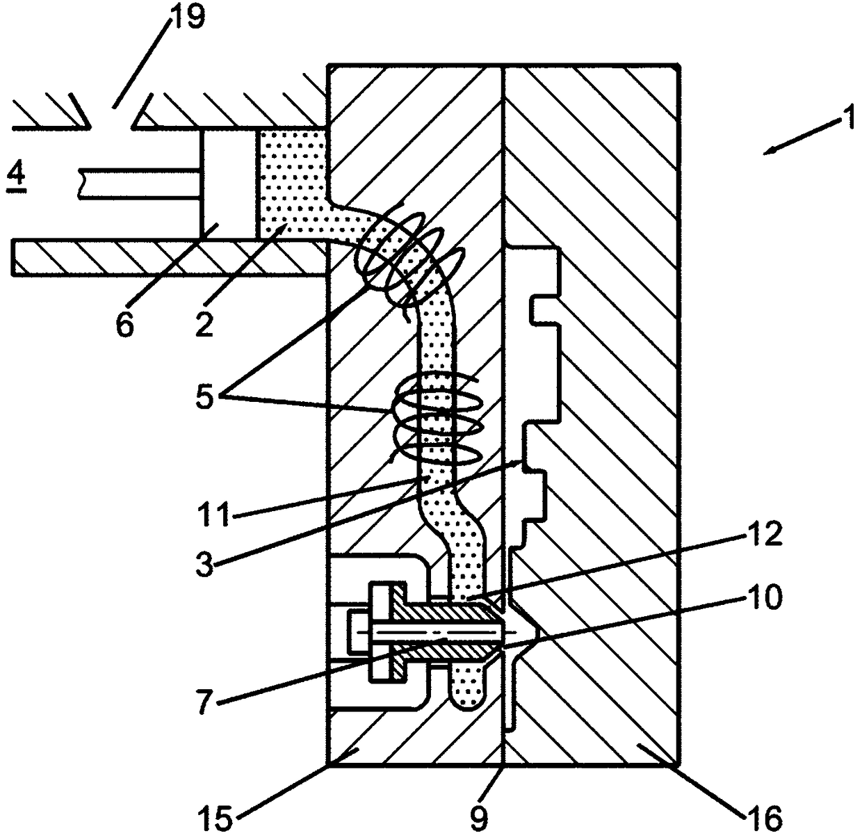
[0040] figure 1 A part of a casting device 1 for die-casting a metal melt 2 such as a magnesium melt or an aluminum melt is schematically shown. The casting device 1 has a casting chamber 4 which can be filled by a melt reservoir (not shown) via a melt valve 19 . The melt 2 is pushed from the horizontally oriented casting chamber 4 via a hydraulically moved casting piston 6 advancing horizontally into a melt channel 11 and is acted upon with pressure.

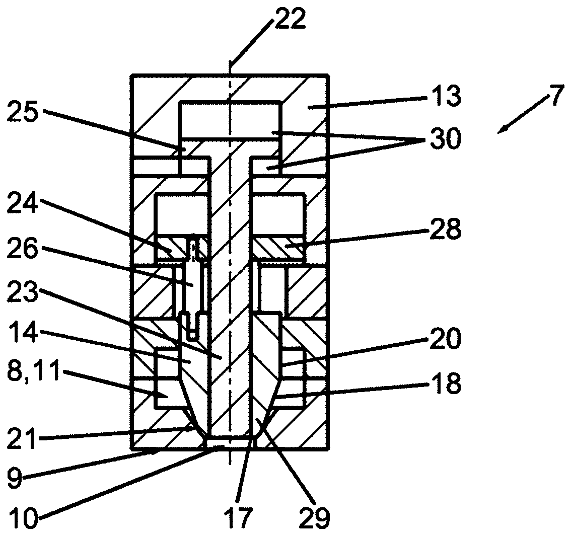
[0041] The melt channel 11 is surrounded by a heating means 5 in the form of a coil which prevents the melt 2 from cooling. From the heated melt channel 11, the melt 2 reaches the valve chamber 8 of the casting valve 7 through a melt channel interface 12 ( figure 2 ) and from there via the valve outlet 10 into the casting cavity 3 . The casting cavity 3 itself is formed by two casting mold half-shells 15, 16 and in a known manner by a negative mold enlarged by the shrinkage allowance (Schwindma β) of the casting to be produ...


PUM


Abstract

A casting valve configured to supply a melt of a casting device includes a valve housing including a melt channel connection as an inlet and a valve outlet as a run-out. A melt channel is configured to be pressurizable via a casting pressure. A valve compartment is configured to receive the melt. The valve compartment is connectable via the melt channel connection with the melt channel. A closing device is configured to modify a cross-sectional surface of the valve outlet. A post-compression piston is configured to post-compress the melt after a completion of a mold filling.

Description

technical field [0001] The invention relates to a casting valve for supplying melt to a casting device, said casting valve having: a valve housing with a melt channel connection as inlet and a valve outlet as outlet; A valve chamber is used to receive the melt; a closing device is used to change the cross-sectional area of ​​the valve outlet. The invention also relates to a casting device having a casting valve of this type and to a casting method for producing cast parts with the casting device. Background technique [0002] Numerous measures are known from the prior art in order to influence the mold filling process of the mold cavity of the cast part. A defined sprue speed (Anschnittgeschwindigkeiten) and gating system is used for each melt type. Since a maximum sprue speed must not be exceeded, the cross-section of the sprue face and thus that part of the gating system which enables separation of the casting part from the die-casting tool after the casting process need...

Claims


Application Information

Patent Timeline
Patent Type & Authority Patents(China)
IPC IPC(8): B22D17/20
CPCB22D27/11B22D17/20B22D17/2015B22D17/203B22D17/2069B22D17/2076B22D17/30
Inventor J·法伦巴赫M·格布格斯M·里希特T·施瓦茨
Owner 舒乐绞扭机有限责任公司
Why Eureka
Try Eureka